


ITX-E16 User`s Manual
25
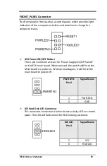
FRONT_PANEL Connector
The front panel of the case has a control panel, which provides light
indication of the computer activities and switches to change the
computer status.
ATX Power ON/OFF Button
This 2-pin connector acts as the “Power Supply On/Off Switch”
on the E16 main board. When pressed, the switch will force the
Main board to power on. When pressed again, it will force the
main board to power off.
PWR BTN
Pin #
Signal Name
1
PWR-BTN
5
GND
IDE Hard Disk LED Connector
This connector connects to the hard drive activity LED on control
panel. This LED will flash when the HDD is being accessed.
IDE LED
Pin #
Signal Name
2
VCC
6
HDDLED
PWRBTN1
HDDLED1
Содержание ITX-E16
Страница 1: ...ITX E16 Intel Core 2Duo 945GME Mini ITX Main Board User s Manual Version 1 0...
Страница 8: ...Contents viii ITX E16 User s Manual This page is intentionally left blank...
Страница 10: ...2 ITX E16 User s Manual Chapter 1 Features Specifications FEATURES 3 SPECIFICATIONS 4...
Страница 17: ...ITX E16 User s Manual 9 Jumper Locations on the ITX E16...
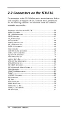
Страница 23: ...ITX E16 User s Manual 15 Connector Locations on the ITX E16...