


Setup Guide
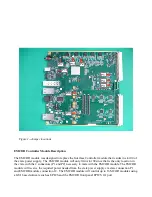
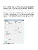
The EMCOR module is properly configured for use before shipment. The following jumper
configuration guide is for reference only and shows how the module should be configured for normal
use. All testing is performed with the jumpers in the following configuration. Table 1 shows the signal
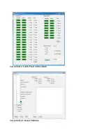
names and jumper configurations. Figure 1 shows the actual location of the jumpers on the module.
The table below does not reference the jumper on P9, which is installed to ensure a predictable CPU
boot-up process.
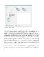
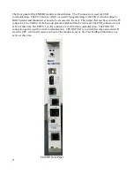
The EMCOR module comes equipped with a CPU module attached (non SLAC customers only). The
CPU must go through a boot up process each time power is applied to the crate before the EMCOR
module can be used to control MCOR modules, unless the USB Diagnostic Application is being used.
Instructions for the CPU boot up process, which loads the OS into the CPU module, can be found later
in this document.
Note that due to the amount of heat generated by the CPU module, it is necessary to always make
certain that a blower assembly is installed to the crate and that air flow is constantly available across
the EMCOR and CPU module as a means to remove heat being generated.
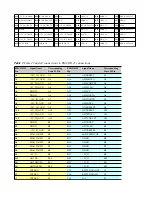
Table 1-
Table of jumper connections on the EMCOR module
Header/Jumper Connection
Pins
Signal 1
Signal 2
Signal 3
Use
P1
1 to 2
+15V_VIN15V_V_IN
+15V Power
P2
2 to 3
+3.3V
+5V_IN
+3.3V Power
P3
1 to 2
+5V_IN_CRATE
+5_VIN
+5V Power
P4
1 to 2
-15V_IN_CRATE -15V_IN
-15V Power
P10
2 to 3
VCCIO
+3.3VCCIO USB Output
VCC
P11
2 to 3
+3.5V_IN
+3.3VCCIO
Power
W3
In
+5V_REF1
+5V_REF1
DAC Ref.
W7
In
DGND
AGND
DGND to
AGND
W8
In
+5V_REF2
+5V_REF2
DAC Ref.
3


