ETC Installation Guide
CueSystem Relay Interface
CueSystem Relay Interface
Page 4 of 5
ETC
Connections
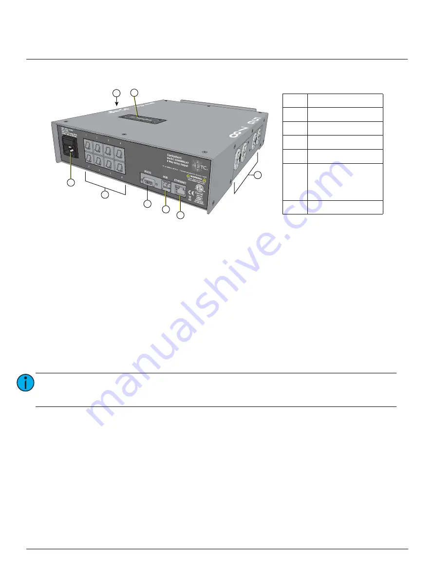
1. Connect an Ethernet cable (not provided) between the “Ethernet” port (E in the illustration above)
and the network switch.
2. Plug the provided IEC power cable into the IEC receptacle (A in the illustration above).
3. Plug loads into the 120 V Edison sockets (F in the illustration above, four on each side).
4. Plug the power input cable into a 120 VAC 50/60 Hz mains power source.
Relay Operation
Use the CueSystem PC application with a CueSystem desk to enable and disable the relays. There are eight
relay LEDs on the front of the enclosure, one for each circuit (see G in the illustration above). An illuminated
green LED means the relay is on.
Circuit Breakers
The circuit breakers (B in the illustration above) will trip if the current drawn by the load exceeds 3 A. Unplug
the load from the relay box and push the circuit breaker button in to reset a tripped output.
Input Fuse
If you overload the relay interface, the 10 A fuse in the input power socket (A in the illustration above) will
blow. When the input fuse is blown, the LEDs near the Ethernet input (E in the illustration above) will not
display any activity and the relay interface outputs will not function.
To replace the fuse:
1. Disconnect the input power cable.
2. Remove the fuseholder using a small flatblade screwdriver.
3. Replace the fuse with a 10 A type T 5x20 mm 250 V fuse.
Note:
The CueSystem Relay Interface supports up to 10 A total connected load; more than three
output circuits cannot be loaded to 3 A at the same time. If you overload the outputs, the
input fuse will blow. To replace a blown fuse, see
below.
B
A
C
D
E
F
F
G
A
120 V power input
B
Eight circuit breakers
C
RS232 port
D
Two USB ports
E
Ethernet RJ45 port
F
Eight 120 V Edison
sockets (four on each
side)
3 A max per circuit
G
Relay LEDs


