ETAS
ES430.1 - User’s Guide
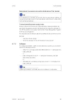
90
8.9
Pin Assignment
This chapter contains information on the following topics:
• ““IN” Connector” on page 90
• ““OUT” Connector” on page 91
• ““Sensor” Connector” on page 92
8.9.1
“IN” Connector
Fig. 8
-
2
“IN” Connector
TIP
All connectors are shown with a view of the front of the ES430.1.
All shields are at case potential.
Pin
Signal
Meaning
1
UBatt
Operating voltage
2
Ground
Ground
3
RX-
Received data, minus
4
TX-
Send data, minus
5
RX+
Received data, plus
6
Ground
Ground
7
UBatt
Operating voltage
8
TX+
Send data, plus
1
7
8


