6
a) Power button: A long push of the power button turns the Mobile Control II
on or off. Starting up the Android system takes about two minutes. A short
press of the power button switches the already active device into standby
mode. If the device is active but the touch screen is dark, a short press of
the power button turns on the display.
b) USB charger socket: This socket serves for connecting a battery charger
respectively for connecting the device to a PC.
c) Motorized throttle knob: The throttle knob with limit stop allows you to
set the desired speed. Turning it anti-clockwise to the limit stop results in a
change of direction. The throttle knob is motorized and follows the requi-
red speed.
d) Touch buttons: There are four system buttons on the touch screen
1. Menu: Calling up App dependent menus.
2. Home: Pressing the Home button changes the display to the Android start
screen at any time.
3. Back: This button causes a step back in the menus or Apps.
4. Emergency Stop: Pressing this button while the Mobile Control App is ac-
tive (!), turns the DC current on or off. One LED (red/green) signals the track
status.
e) Headphone Jack: This 3.5mm jack serves for connecting a headset (Nokia
or Samsung compatible). Besides two stereo speakers one can also connect
a microphone.
f) Charging gauge: displays the battery status.
g) WLAN display: Shows the WLAN signal strength.
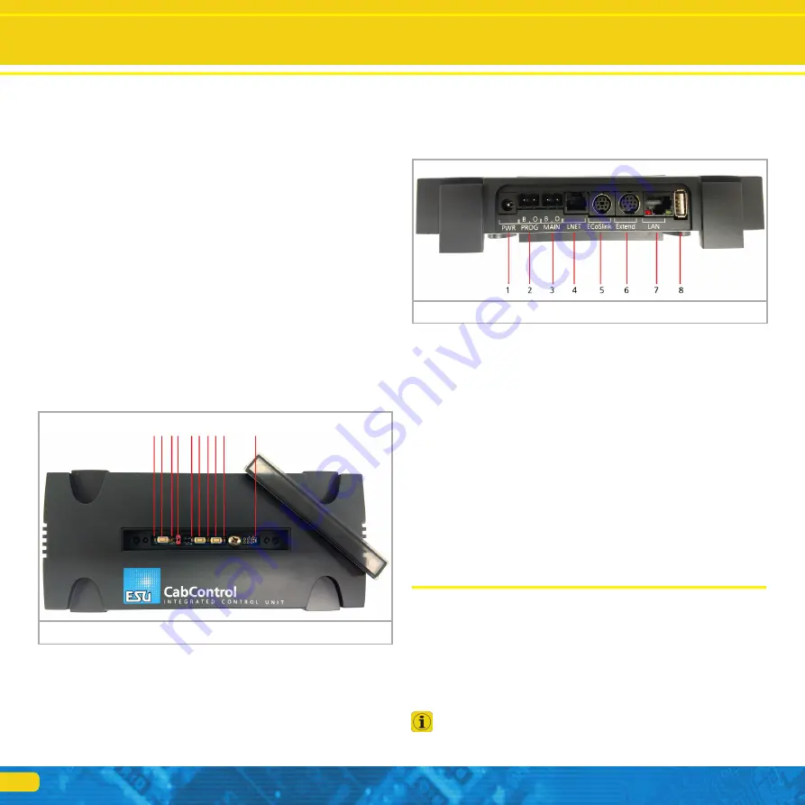
6.1. Integrated Control Unit
Integrated Control Unit
6) Button for System Reset/Back Up
7) Status LED for System Reset/Back Up
8) Button for Rescue/Update
9) Status LED for Rescue/Update
10) Status LED for Power to the System. If Light is on, Power is applied
1) 5.5mm socket for Power Supply
2) Programming Track - Hook up Programming Track here.
3) Main Track – Hook up Main Layout Track here.
4) L-Net socket - L-Net connection not currently active at time of printing. Can
be turned on with a future update
5) ECoSlink socket – EcoSlink Bus Line
6) Extended socket – Connect additional ESU compatible components
7) LAN (Local Area Network) Connection. Ethernet to Computer
8) USB socket for Updates and Mobile Control II Charging.
6.2. Network Settings
The CabControl network settings are not customizable. It will always have
the same default settings when connecting to a network. In the interest of
functional security and reliability we do not provide a user interface to adjust
the network settings.
6.3. Updates to the CabControl System
Updates can easily be applied to the system via the USB connection through
a USB Data Stick.
7. Unpacking & connecting - Getting Started!
7.1. Battery
The Mobile Control II is powered by an integral Lithium Polymer rechargeable
battery generally good for 3 to 5 hours operating time. The charger cable is
plugged into the micro USB socket at the bottom of the device. Connect this
socket with the supplied USB charger cable with any USB charger or directly
with the USB port on the back of the CabControl ICU. You may use any of
the commercially available USB chargers. Charging to a full load takes about
two to three hours.
We recommend to fully charging the batteries prior to initial use
and not turning on the device before the batteries are fully char-
ged.
Connections
Figure 4: Integrated Control Unit Back
1) Status LED for WPS connection (Wi-Fi connection via “Push Button”)
2) Button for WPS connection
3) Blue status LED for active connection between the ICU and Mobile Control
II Throttle. Lights up when CabControl App is active and connected to the
ICU
4) Jumper to turn Wi-Fi On and Off
5) Status LED for Track Power. (Blinks if track power is OFF. Steady on Green
when Track Power is ON.)
Figure 3: Integrated Control Unit Top
1. 2. 3. 4. 5. 6. 7. 8. 9. 10.
Содержание CabControl DCC System
Страница 1: ...1 User manual 1 Edition November 2017 CabControl DCC System...
Страница 28: ...28 ESU P N 00717 18804...


