MC404-Z
Document Version: 1.05
© 2021 All rights reserved.
9
Consecutive movements may be merged to produce continuous path motion and the user
may program the motion using programmable units of measurement (e.g. mm, inches, revs
etc.). The module may also be programmed to control only the axis speed. The positioner
checks the status of end of travel limit switches which can be used to cancel moves in
progress and alter program execution.
LED indicators
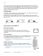
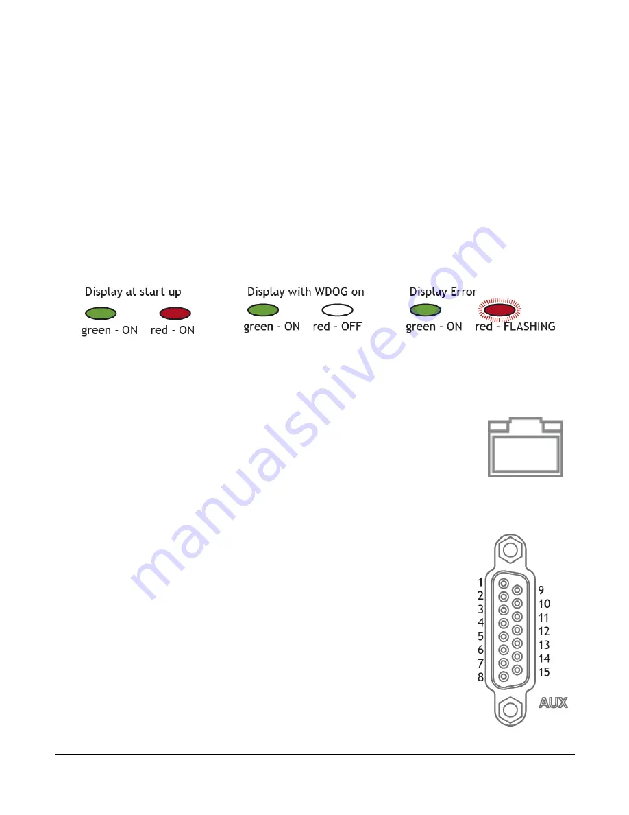
2 LEDs show the status of the power and the enable circuit. The enable circuit drives the
watchdog relay and activates the pulse output signals.
Red LED ON shows that the WDOG is off and the axes are disabled. When the red LED is
OFF, the axes are enabled and ready to move. A flashing red LED indicates that one or more
axes are in error.
Connections to the MC404-Z
Ethernet port connection
RJ45 socket 10/100 base_T
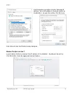
The Ethernet port is the default connection between the Motion
Coordinator and the host PC running the Motion Perfect development
application.
Serial connections
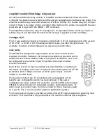
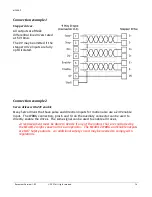
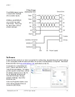
The MC404-Z features two serial ports. Port 1 is a standard RS232 serial connection and Port
2 is configurable as RS422 or RS485 by external wiring. Both ports are
accessed through the 15-way auxiliary connector.
The serial ports are not isolated therefore the 0V terminal MUST be
connected.
CANbus connections
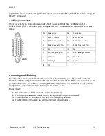
A CANbus port for connection to
Trio’s digital and analogue CAN I/O
expansion modules is provided on the auxiliary connector. CAN-H on pin7
and CAN-L on pin 15.
The CANbus port is not isolated therefore the 0V terminal MUST be
connected.

