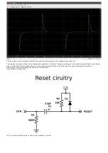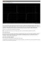
As you can see, the 6.6V peak is now very narrow, just like we wanted. It's impossible to discharge the capacitor instantly, that would
require a capacitor and a diode with 0Ω of series resistance, and an infinite current, which is impossible, obviously. There's also a
smaller but relatively wide peak of approximately 3.9V. This is because a diode only conducts when the voltage across it is higher than
~600mV. This means that the last 0.6V that's left in the capacitor (from 3.9 to 3.3V) will still be discharged through R2 only.
Nevertheless, the voltage peak is much lower and narrower than without the diode, and it's safe to connect to the ESP8266.
This exact circuit is also used in the Arduino Uno, for example.
Note: if you followed the instructions in the hardware step correctly, you should already have added R2 to your ESP.
How to use Auto-reset
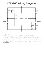
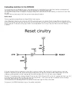
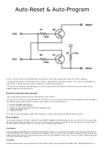
To use this auto-reset circuit, connect it to the DTR line of your USB-to-Serial converter, and to the reset line of the ESP, as shown in
the diagram. Then click compile (just because the first compilation can take quite some time). Go to Tools > Reset and select 'ck'.
When it's done compiling, hold down the program button we added in the hardware step, and click upload. Wait for it to say
"Uploading..." and then release the program button.
Auto-reset and Auto-program
This only applies to boards without an on-board USB-to-Serial converter.
The method above still requires you to press a button to upload a new sketch. If your USB-to-Serial converter has a RTS line as well as
a DTR line, you can automate the entire process.
Содержание ESP8266 SDK
Страница 4: ......
Страница 22: ......
Страница 32: ...It automatically detected that it had to send the compressed versions of index html and favicon ico ...
Страница 50: ......

