


Hardware-Installation
CAN-CBX-REL4
Manual • Doc.-No.: C.3012.21 / Rev. 1.1
Page 15 of 99
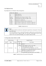
3.2.2 Indicator States
In principle there are 8 indicator states distinguished:
Indicator state
Display
on
LED constantly on
off
LED constantly off
blinking
LED blinking with a frequency of approx. 2.5 Hz
flickering
LED flickering with a frequency of approx. 10 Hz
1 flash
LED 200 ms on, 1400 ms off
2 flashes
LED 200 ms on, 200 ms off, 200 ms on 1000 ms off
3 flashes
LED 2x (200 ms on, 200 ms off) + 1x (200 ms on, 1000 ms off)
4 flashes
LED 3x (200 ms on, 200 ms off) + 1x (200 ms on, 1000 ms off)
Table 6: Indicator states
Note:
Red and green LEDs are strictly switched in phase opposition according to the CANopen
Specification [3].
For certain indicator states viewing all LEDs together might lead to a misinterpretation
of the indicator states of adjacent LEDs. It is therefore recommended to look at the
indicator state of an LED individually, in covering the adjacent LEDs.
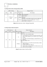
3.2.3 Operation of the CAN-Error LED
LED indication
Display function
Label
Name
Colour
Indicator
state
Description
E
CAN Error
red
off
no error
1 flash
CAN controller is in Error Active state
on
CAN controller state is Bus Off
(or coding switch position ID-node > 7F
h
when
switching on; see ’Special Indicator States’on page 17)
2 flashes
Heartbeat or Nodeguard error occurred.
The LED automatically turns off, if
Nodeguard/Heartbeat-messages are received again.
Table 7: Indicator states of the red CAN Error-LED


