


Wiring Notes
CAN-CBM-Clock
Hardware Manual • Doc.-No.: C.2836.21 / Rev. 1.3
Page 27 of 34
¡
¢
£ ¤
¥ ¤
£ ¤
¥ ¤
£ ¤
¥ ¤
£ ¤
¥ ¤
£ ¤
¥ ¤
£ ¤
¥ ¤
£ ¤
¥ ¤
£ ¤
¥ ¤
£ ¤
¥ ¤
£ ¤
¥ ¤
¦§
¨ ©ª
¦§¨©«
¦§
¨ ©¬ ¨
®¯° ±²³
¦§
¨ ©¬ ¨
´µ¶·´
¸
¹
´µ¶·´¸ ¹
º
»
¼
½
¾
¿
À
Á
Â
½
¿
À
º
»
¼
Á
¾
Â
£ ¤
¥ ¤
£ ¤
¥ ¤
®° ÃÄ ²±
Å
¯
°±²³ ±³
³ ÆÇ È² ±
ÉÊ °ÅÉ ±
³
Ë Ì°Í
Î
ÌÈ ² ±
Ï Ð
Æ ÇÍÑ Ê°Í±
ÎÌȲ ±Ò
ÓÔ
ÓÔ
ÕÖÓÓ× ×
Ø Ù
ÚÛÜ
Ý
Þß ÛÝàá
â ãäå
æ çèé ê
ë
ì íîïð ñ
òóô
õ ãö ÷çø
çù ù
ã ö÷ ú å÷ë
éû
ùã÷ öø å
ù üã åøý åý
ýéê þ øå
ë
ÿ ãùëåý
çãä
çþ øå
ÿ ã ëü
å
ç äëü
ç
÷ ý
ëåäú ã ÷çëã é÷
£¤¥ ¤
£
¥ ££Ý
¥
Ý á
¸ ´
¸
¸
¸
¶
¹ ¸ ·¶ ´
¶
¸ ´
¸
¸
¸
¶
¹ ¸ ·¶
´
¶
!"
#
$ %
ó ï&
'(
ì) íô
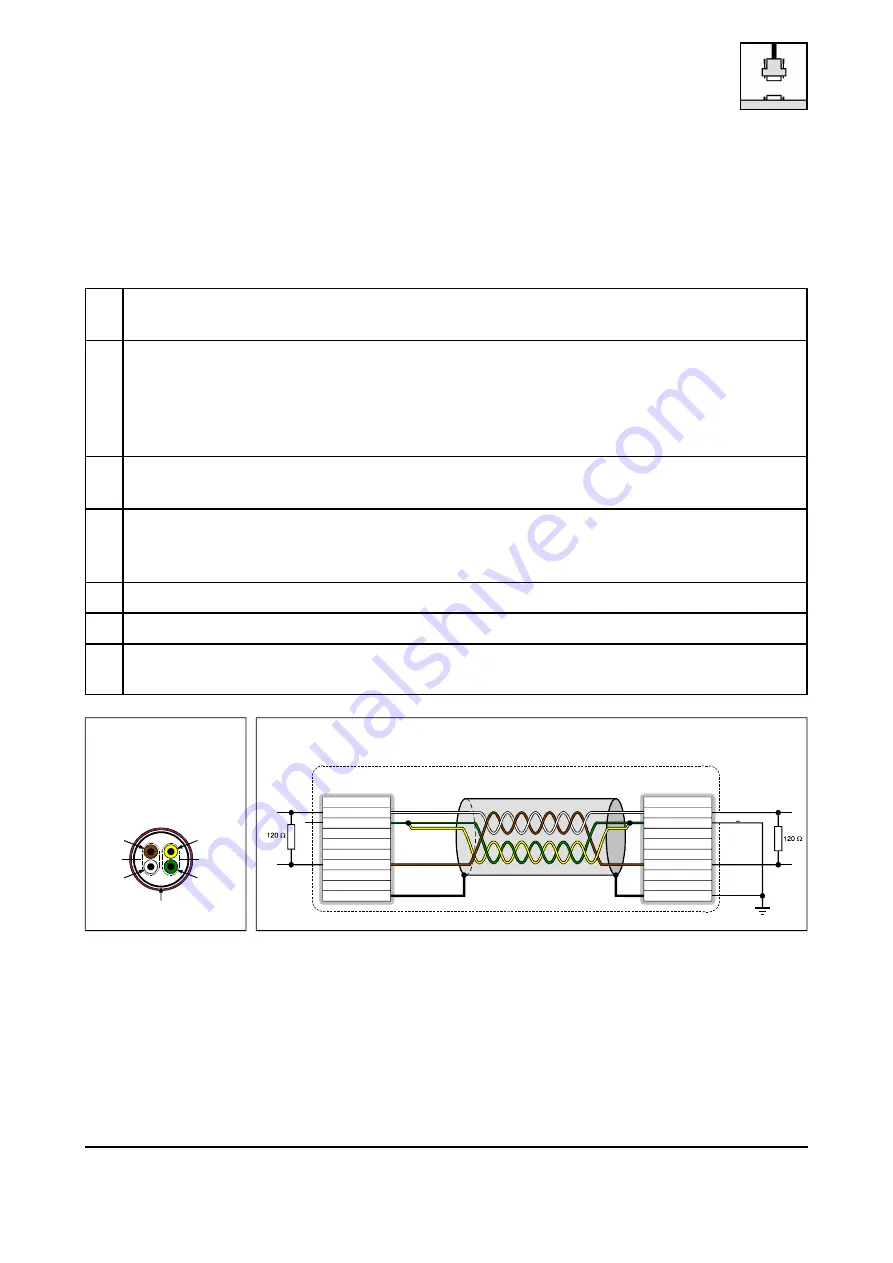
6.3 Heavy Industrial Environment (Double Twisted Pair Cable)
6.3.1 General Rules
The following general rules for CAN wiring with single shielded double twisted pair cable should be
followed:
1
A cable type with a wave impedance of about 120
*
±10% with an adequate conductor cross
section (
+
0.22 mm²) has to be used. The voltage drop over the wire has to be considered.
2
For heavy industrial environment use a four-wire CAN cable.
Connect
,
two twisted wires to the data signals (CAN_H, CAN_L) and
,
the other two twisted wires to the reference potential (CAN_GND) and
,
the cable shield to functional earth (FE) at least at one point.
3
The reference potential CAN_GND has to be connected to the functional earth (FE) at
exactly one point.
4
A CAN bus line must not branch (exception: short cable stubs) and has to be terminated with
the characteristic impedance of the line (generally 120
*
±10%) at both ends (between the
signals CAN_L and CAN_H and not to CAN_GND).
5
Keep cable stubs as short as possible (l < 0.3 m).
6
Select a working combination of bit rate and cable length.
7
Keep away CAN cables from disturbing sources. If this cannot be avoided, double shielded
cables are recommended.
Fig. 8: CAN wiring for heavy industrial environment