


Wiring Notes
CAN-CBM-Clock
Hardware Manual • Doc.-No.: C.2836.21 / Rev. 1.3
Page 25 of 34
! "#
$%
&' ()
*+
, -.
* +
,-/
*+
, -0 ,
1
23 45 67
8
9
376: 7:
;< 38;7:
= >3?
@
>A 6 7
B;< CD <3?7
@>A6 7E
FG
H
G
IJH HK
K L
M
NO P
QRST
U VRT W
XY
Z [\]
^ _`a b
c
d [e f_g
_h h
[
e
f i ]fc
aj
h[f eg ]
h k[ ]gl ]l
cm[ h
c ]
l
n _[ \
o_ pg ]
m[ c
k
] _
\ ck
_fl
c]\ i [f _
c[ af
q
r P
r T
PT X
st u
vw
xy zz{ x |
y }
~{
{
y}
{
z
{ z
|
yz
st u
vw
xy zz{ x |
y }
~{
{
y}
{
z
{ z |
y z
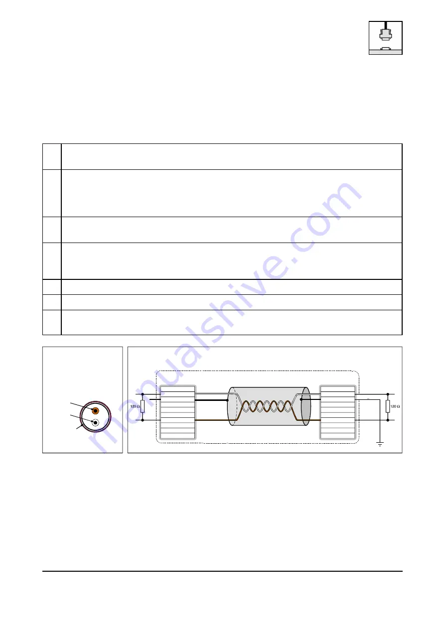
6.2 Light Industrial Environment (Single Twisted Pair Cable)
6.2.1 General Rules
The following general rules for CAN wiring with single shielded single twisted pair cable should be
followed:
1
A cable type with a wave impedance of about 120
±10% with an adequate conductor cross-
section (
0.22 mm²) has to be used. The voltage drop over the wire has to be considered!
2
For light industrial environment use at least a two-wire CAN cable.
Connect
the two twisted wires to the data signals (CAN_H, CAN_L) and
the cable shield to the reference potential (CAN_GND).
3
The reference potential CAN_GND has to be connected to the functional earth (FE) at
exactly one point.
4
A CAN net must not branch (exception: short cable stubs) and has to be terminated with the
characteristic impedance of the line (generally 120
±10%) at both ends (between the signals
CAN_L and CAN_H and not at CAN_GND)!
5
Keep cable stubs as short as possible (l < 0.3 m)!
6
Select a working combination of bit rate and cable length.
7
Keep away cables from disturbing sources. If this cannot be avoided, double shielded wires are
recommended.
Figure. 6: CAN wiring for light industrial environment