


i
Overview
Hardware Manual • Doc.-No.: C.3010.21 / Rev. 1.3
CAN-CBM-Clock
Page 10 of 34
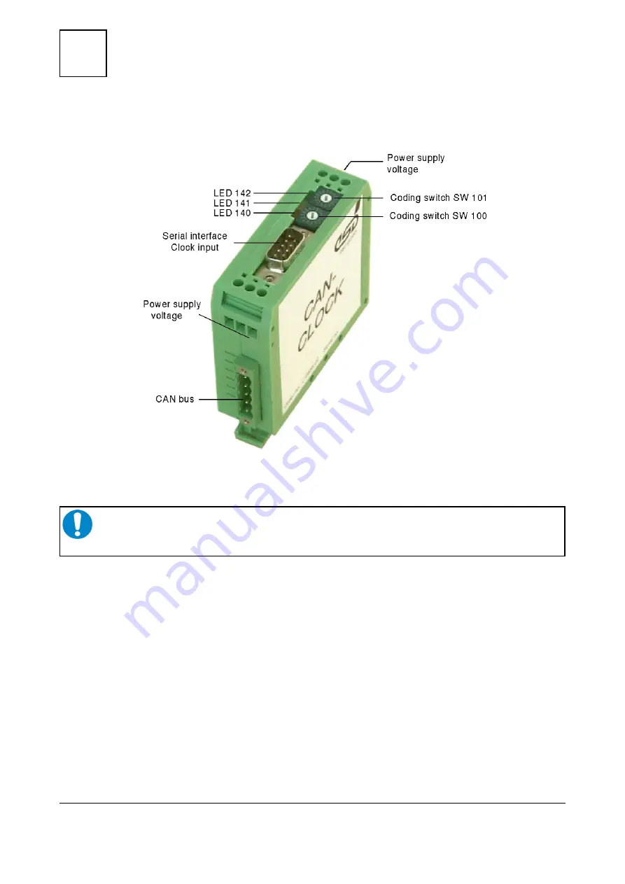
1.2 View of the Module with Connectors and Coding Switches
Figure 2: Position of the connectors and coding switches
NOTICE
Read chapter “Quick Start” on page 19, before you start with the installation of the
hardware!