User Manual
14
INSTALLATION PROCEDURE
• When fitting the cooktop with a rangehood above, refer to the installation requirements
of the rangehood for clearances required.
• This appliance is to be built into a kitchen unit or 600mm worktop, provided the
following minimum distances are allowed;
• The edges of the cooktop must be a minimum distance of 60mm from a side or rear wall.
• Adjacent walls, cupboards and protection for combustible materials: Ensure that the
appliance is installed in accordance with AS/NZS 5601.1, or AS/NZS 5601.2 with regard
to clearances to combustible surfaces and materials, and clearances to rangehoods and
exhaust fans.
• Clearances to combustible surfaces may be reduced if combustible surfaces are
protected in accordance with AS/NZS 5601.1, or AS/NZS 5601.2.
• 400mm between the cooktop surfaces, providing that the underside of the horizontal
surface is in line with the outer edge of the cooktop. If the underside of the horizontal
surface is lower than 400mm, then it must be at least 50mm away from the outer edges
of the cooktop.
• 50mm clearance around the appliance and between the cooktop surface and any
combustible materials.
• A barrier must be installed to prevent accidental contact with the cooktop base,
where the base of the cooktop is accessible from below (i.e. Inside a cupboard, etc.).
A minimum clearance of 25mm must be maintained between the base and the barrier.
This barrier may be made of any non-combustible, rigid material.
• You must have a gap of at least 25mm and at most 74mm between the underneath of
the appliance and any surface that is below it.
• Barrier protection is not necessary if the product is installed above an underbench oven
or similar appliance and/or if the cupboard construction is such that the underside of
the cooktop is not accessible.
• An oven must have forced ventilation to install a cooktop above it. Check the dimensions
of the oven in the installation manual.
• The cut out size must obey the indication.
• Ensure that there is an earthed power outlet within 900mm of the rear right hand side of
the cooktop when installed. This should be accessible at all times.
• A self-adhesive Foam Tape has been provided to act as a sealing agent and is to be
placed around the edge of the hob underside. Ensure that there are no gaps in the Foam
Tape. Take care to ensure that the seals meet without overlapping. The thickness of this
Foam Tape is 3mm and the width is 10mm.
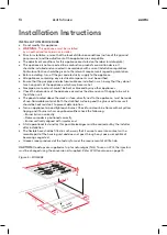
Positioning
The edges of the hob must be a minimum distance of mm from a side or
rear wall.
700 mm between the highest point of the hob surface (including the burners)
and the underside of any horizontal surface directly above it.
400 mm between the hob surfaces, providing that the underside of the
horizontal surface is in line with the outer edge of the hob. If the underside of
the horizontal surface is lower than 400 mm, then it must be at least 50 mm
away from the outer edges of the hob.
50 mm clearance around the appliance and between the hob surface and any
combustible materials.
45 mm
60
You must have a gap of at least 25 mm and at most 74 mm between
the underneath of the appliance and any surface that is below it.
16
o
o
o
o
o
CLEARANCES REQUIRED
WHEN FITTING THE HOB
WITH A COOKER HOOD ABOVE
90
0mm
700mm
400mm
400mm
FO 0813
60mm
480mm
in0.0mm
M
2
This appliance is to be built into a kitchen unit or 600mm worktop,providing
the following minium distances are allowed;
- An oven must have forced ventilation to install a hob above it.
- Check the dimensions of the oven in the installation manual.
- The cut out size must obey the indication.
830mm
1 2
INSTALLATION INSTRUCTIONS CONT.
INSTALLING THE APPLIANCE
• Remove the pan supports, the burner lid and
flame spreader and carefully turn the appliance
upside down and place it on a cushioned mat.
Take care that the Ignition devices and flame
supervision devices are not damaged in this
operation.
• Apply the sponge provided around the edge of
the appliance.
• Do not leave a gap in the sealing agent or
overlap the thickness.
WARNING!
DO NOT use a silicon sealant to seal the appliance
to the bench top.
This will make it difficult to remove the appliance
from the aperture in future, particularly if it needs to
be serviced.
1. Place the bracket (B) over the holes that match
the size of the screws. There are one set of screw
holes in each corner of the cooktop.
2. Slightly tighten a screw (C) through the bracket
(B) so that the bracket is attached to the hob, but
so that you can still adjust the position. Carefully
turn the hob back over and then gently lower it
into the aperture hole that you have cut out.
3. On the underneath of the hob, adjust the
brackets into a position that is suitable for
your worktop.
Then fully tighten the screws (C) to secure the hob
into position.
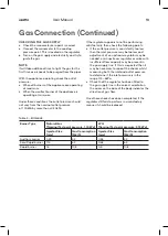
Installing the appliance
Bottom view
of the screws.There are one set of screw holes in each
corner of the hob
(H)
.
Slightly tighten a screw
(C) through the bracket
(B) so
that the bracket is attached to the hob, but so that you
can still adjust the position .
.
2 Carefully turn the hob back over and then gently lower
it
into the aperture hole that you have cut out.
.
3 On the underneath of the hob, adjust the brackets into
a
position that is suitable for your worktop.
Then fully tighten the screws
(C) to secure the hob into
position.
(A) SEALING STRIP
(C) SCREW
(B) BRACKET
17
Remove the pan supports, the burner lid
and flame spreader and carefully turn the
appliance upside down and place it on a
cushioned mat.
Take care that the Ignition devices and
flame
supervision devices are not damaged
in this operation.
2. Apply the sponge provided around the
edge of
the appliance.
3.
1.
Do not leave a gap in the sealing agent or
overlap the thickness.
3ODFHWKHEUDFNHW
%RYHUWKHKROHVWKDWPDWFKWKHVL]H
7KLVZLOOPDNHLWGLI¿FXOWWRUHPRYHWKH
DSSOLDQFHIURPWKHDSHUWXUHLQIXWXUH
SDUWLFXODUO\LILWQHHGVWREHVHUYLFHG
Do not use a silicon sealant to seal the
appliance against the aperture.
Installing the appliance
of the screws.There are one set of screw holes in each
corner of the hob
(H)
.
Slightly tighten a screw
(C) through the bracket
(B) so
that the bracket is attached to the hob, but so that you
can still adjust the position .
.
2 Carefully turn the hob back over and then gently lower
it
into the aperture hole that you have cut out.
.
3 On the underneath of the hob, adjust the brackets into
a
position that is suitable for your worktop.
Then fully tighten the screws
(C) to secure the hob into
position.
(A) SEALING STRIP
(C) SCREW
(B) BRACKET
17
Remove the pan supports, the burner lid
and flame spreader and carefully turn the
appliance upside down and place it on a
cushioned mat.
Take care that the Ignition devices and
flame
supervision devices are not damaged
in this operation.
2. Apply the sponge provided around the
edge of
the appliance.
3.
1.
Do not leave a gap in the sealing agent or
overlap the thickness.
3ODFHWKHEUDFNHW
%RYHUWKHKROHVWKDWPDWFKWKHVL]H
7KLVZLOOPDNHLWGLI¿FXOWWRUHPRYHWKH
DSSOLDQFHIURPWKHDSHUWXUHLQIXWXUH
SDUWLFXODUO\LILWQHHGVWREHVHUYLFHG
Do not use a silicon sealant to seal the
appliance against the aperture.
Installation Instructions (Continued)

