background image

ESAB FABRICATOR 141i

ASSEMBLY PROCEDURES                                                                 8-4                                                                               Manual 0-5448  

6

Art # A-12183

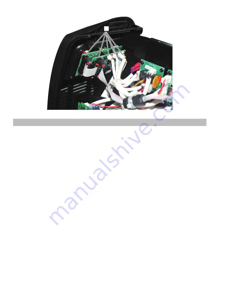
8.04  Installing Control PCB2 and Clear Protective Sheet

1.  Install 4 screws.
2  Plug harness into DRIVE connector.
3.  Plug harness into SOURCE connector.
4.  Plug harness into CR connector.
5.  Plug harness into FUNs connector
6.  Plug harness into NTCs connector.
7.  Plug harness into IGBT OT connector .
8.  Plug harness into GUN connector.
9.  Plug harness into QF/DY connector.
10. Plug harness into WVIN connector.
11  Plug harness into MB connector.
12. Plug harness into PWM connector.
13. Plug harness into IFB connector.
Verify harness connections with the system schematic to ensure all connections are correct.
14. Install clear protective sheet.

Содержание fabricator 141i

Страница 1: ...3163339 R vision AA Issue Date September 17 2015 Manual No 0 5448 Service Manual ESAB Fabricator 141i 3 IN 1 Multi Process Welding Systems esab com...

Страница 2: ...take the time to read the entire manual especially the Safety Precautions They will help you to avoid potential hazards that may exist when working with this product YOU ARE IN GOOD COMPANY The Brand...

Страница 3: ...ts reserved Reproduction of this work in whole or in part without written permission of the publisher is prohibited The publisher does not assume and hereby disclaims any liability to any party for an...

Страница 4: ...reof contained in this manual and accom panying labels and or inserts when installed operated maintained and repaired in accordance with the instructions provided This equipment must be checked period...

Страница 5: ...ION 4 OPERATION 4 1 4 01 Power Source Controls Indicators and Features 4 1 4 02 Attaching the Fusion 140A MIG Gun 4 7 4 03 Inserting Wire into the Wire Feed Mechanism 4 8 4 04 Installing 4 100mm Diame...

Страница 6: ...on 6 22 6 15 Circuit Diagram 6 24 SECTION 7 DISASSEMBLY PROCEDURE 7 1 7 01 Safety Precautions for Disassembly 7 1 7 02 Control PCB2 Removal 7 1 7 03 Display PCB3 Removal 7 3 7 04 Front Panel Assembly...

Страница 7: ...arted up no one is unprotected when the arc is struck 3 The workplace must be suitable for the purpose be free from drafts 4 Personal safety equipment Always wear recommended personal safety equipment...

Страница 8: ...lter lens and wear protective clothing Protect bystanders with suitable screens or curtains FIRE HAZARD Sparks spatter can cause fire Make sure therefore that there are no inflammable materials nearby...

Страница 9: ...ollow ing instructions detail how to correctly and safely set up the machine and give guidelines on gaining the best efficiency and quality from the Power Source Please read these instructions thoroug...

Страница 10: ...mediately Should such repairs or replacements become necessary it is recommended that such repairs be carried out by appropriately quali fied persons approved by ESAB Advice in this regard can be obta...

Страница 11: ...at a 20 duty cycle 100 amperes at 19 volts This means that it has been designed and built to provide the rated amperage 100 A for 2 minutes i e arc welding time out of every 10 minute period 20 of 10...

Страница 12: ...elding Current Range STICK Mode 10 90A Wirefeed Speed Range 95 390 IPM MIG Welding Voltage Range 10 19V DC Nominal OCV 53V DC Breaker Size 20A 30A Requires updated Power Cord and Plug Effective Input...

Страница 13: ...ed kneel ing sitting or lying position with physical contact with conductive parts 2 In locations which are fully or partially limited by conductive elements and in which there is a high risk of unavo...

Страница 14: ...padlocking line disconnect switch in open position removing fuses from fuse box or shutting off and red tagging circuit breaker or other disconnecting device Electrical Input Requirements Operate the...

Страница 15: ...could occur if 140V AC or higher is applied to the Primary Power Cord Model Primary Supply Cord Size Factory Fitted Minimum Primary Current Circuit Size Vin Amps Current Duty Cycle MIG GMAW FCAW STIC...

Страница 16: ...wer Source enclosure 2 Maintenance of Welding Equipment The welding equipment should be routinely maintained according to the manufacturer s recommendations All access and service doors and covers sho...

Страница 17: ...tream equipment is compatible with the maximum delivery pressure of the flowmeter regulator 4 Be sure that the flowmeter regulator has the correct pressure rating and gas service for the cylinder used...

Страница 18: ...quired on the cylinder valve to turn off the cylinder quickly if necessary 10 Attach the desired downstream equipment 3 09 Volt Ampere Curves Voltage Amperage Curves shows maximum voltage and amperage...

Страница 19: ...ESAB FABRICATOR 141i Manual 0 5448 3 9 SAFETY AND INSTALLATION Notes...

Страница 20: ...ESAB FABRICATOR 141i SAFETY AND INSTALLATION 3 10 Manual 0 5448 This Page Intentionallly Blank...

Страница 21: ...OPERATION SECTION 4 OPERATION 4 01 Power Source Controls Indicators and Features 3 4 5 8 7 10 11 12 13 14 2 1 16 15 A 13037 6 9 Figure 4 1 Front Panel Figure 4 2 Rear Panel 18 19 20 21 Art A 10355 Fi...

Страница 22: ...ode of the welding arc ie dip versus spray transfer Where exact settings are required in the case of procedural work it is recommended that alternate measurement methods be utilized to ensure output v...

Страница 23: ...via 25mm Dinse style connector It is essential however that the Dinse adapter and male plug are inserted and turned securely to achieve a sound electrical connection CAUTION Loose welding terminal con...

Страница 24: ...0 maximum arc force allows greater penetration control to be achieved Arc force is increased by turning the control knob clockwise or decreased by turning the knob counterclockwise When LIFT TIG Mode...

Страница 25: ...voltage value for a period of approximately 10 seconds in all modes The voltage meter will hold the value until 1 any of the front panel controls are adjusted in which case the Power Source will rever...

Страница 26: ...rigger will operate at all times on the remote control socket irrespective of the position of the local remote switch ie in both local and remote modes Should a remote device be connected and the loca...

Страница 27: ...and tightening the Locking Screw to secure the MIG Gun in the MIG Gun Adapter Connect the 8 pin plug by aligning the keyway then inserting the 8 pin plug into the 8 pin socket and rotate threaded col...

Страница 28: ...e pressure roller arm and wire drive tension screw and adjust the pressure accordingly Figure 4 6 Remove the nozzle and contact tip from the MIG Gun With the MIG Gun lead reasonably straight feed the...

Страница 29: ...Nylon Insert Spring Plastic Spacer Brass Flat Washer Flat Washer Figure 4 8 4 100mm Diameter Spool Installation 4 05 Installing 8 200mm Diameter Spool As delivered from the factory the Power Source is...

Страница 30: ...crew These devices should be ad justed to a minimum pressure that will provide satisfactory wire feed without slippage If slipping occurs and inspection of the wire contact tip reveals no wear distort...

Страница 31: ...etaining Screw Feed Roll Art A 09584_AC Figure 4 11 Changing the Feed Roll 4 08 Wire Reel Brake The wire reel hub incorporates a friction brake which is adjusted during manufacture for optimum breakin...

Страница 32: ...up to ten seconds or more depending upon the length and size of the hose being purged Adjusting Flow Rate With the flowmeter regulator ready for operation adjust working flow rate as follows 1 Adjust...

Страница 33: ...hen connect the shielding gas hose from the rear of the Power Source to the flowmeter regulator outlet F Refer to the Weld Guide located on the inside of the wirefeed compartment door for further info...

Страница 34: ...s inserted and turned securely to achieve a sound electrical connection D Refer to the Weld Guide located on the inside of the wirefeed compartment door for further information E Switch the LOCAL REMO...

Страница 35: ...terminal Welding current flows from the Power Source via Dinse style connectors It is essential however that the male plug is inserted and turned securely to achieve a sound electrical connection C Co...

Страница 36: ...the Power Sources Amperage control or REMOTE for remote amperage using a Foot Control Art A 11576_AB MIG Torch polarity lead not connected Note A Tweco 17V TIG torch with an 8 pin plug must be used t...

Страница 37: ...ectors It is essential however that the male plug is inserted and turned securely to achieve a sound electrical connection WARNING Before connecting the work clamp to the work and inserting the electr...

Страница 38: ...nit should be removed 1 Place unit on its back A 12958 2 Remove 2 screws in bottom of the front panel A securing block will become detached and fall free from the front panel as you turn each screw ou...

Страница 39: ...arm and tension knob hang downwardly Art A 11484 Pressure Arm Tension Knob 4 Gently push the bottom of the front panel upward until the thumb screw is fully exposed Art A 11485_AB Thumb Screw Fully E...

Страница 40: ...ESAB FABRICATOR 141i OPERATION 4 20 Manual 0 5448 This Page Intentionally Blank...

Страница 41: ...sformer than in a conventional power supply The AC is then rectified to extremely smooth DC The diagram to the below shows the basic electrical wiring of a DC output inverter power supply Inverter Tec...

Страница 42: ...ESAB FABRICATOR 141i THEORY OF OPERATION 5 2 Manual 0 5448 Notes...

Страница 43: ...recognizable tactile on off position If either switch does not switch properly check that the appropriate switch activators located behind the overlay are aligned properly Turn the three potentiomete...

Страница 44: ...r E No open circuit voltage 1 Defective Main PCB1 a Replace Main PCB1 2 Broken wire in machine a Check and replace 3 Defective Control PCB2 a Replace Control PCB2 F Once the electrode touches the work...

Страница 45: ...r negative welding output terminal as appropriate 2 Poor or no work lead contact a Clean work clamp area and ensure good electri cal contact E Inconsistent wire feed 1 Fouled contact tip a Replace con...

Страница 46: ...s from the front rear mouldings b Remove the centre screws from the front rear mouldings c Loosen slightly the two bottom screws from the front rear mouldings d Remove the three bottom screws and the...

Страница 47: ...cause burning or arcing of PCB trans formers switches or rectifier when a failure occurs Carefully inspect all components within these units Look in particular for the following a Loose or broken wir...

Страница 48: ...s Positive meter lead to testpoint 5 Negative meter lead to testpoint 6 0 2 0 8 VDC Right Output Diodes Positive meter lead to testpoint 7 Negative meter lead to testpoint 8 0 2 0 8 VDC Table 6 2 Outp...

Страница 49: ...ohms Inrush PTC Multimeter Lead Placement Impedance PTC Positive meter lead to testpoint 21 Negative meter lead to testpoint 22 80 to 120 Table 6 5 Inrush PTC Multimeter set to measure ohms 6 08 Chec...

Страница 50: ...IGBT s Multimeter set to measure Diode Voltage Measurements may be made directly onto the main input rectifier AC1 and AC2 may be measured from the pins on the mains supply plug with the main power s...

Страница 51: ...W05 2 MD COUT2 COUT1 OUT OUT T20 1 T13 1 T14 1 T15 1 R100 R102 C100 T16 1 T17 1 R101 DC DC TR8 QF FJ GAS CY1 R25 T4 AC OUT AC OUT IN Header Pin Pin Function Signal 1 15V 15 VDC 2 IGBT 1 4 PWM Driver...

Страница 52: ...Function Signal 1 24V power source 21 25VDC 2 Common of 24VDC and 24VDC 0V 3 24V power source 21 25VDC Table 6 13 DY2 Header Pin Function Connects to SOURCE header on Control PCB2 DY1 Header Pin Pin F...

Страница 53: ...Pin Function Signal 1 PWM Common 0VDC 2 Motor PWM Driver signal 5V Vpk Table 6 17 PWM Header Pin Function Connects to PWM header on Main PCB1 QF DY Header Pin Pin Function Signal 1 Not used n c 2 Sol...

Страница 54: ...signal 4V 300A 4 0V 0V Table 6 22 IFB Header Pin Function Connects to welding output current sensor SOURCE Header Pin Pin Function Signal 1 24V power source 21 25VDC 2 Common of 24V and 24V 0V 3 24V...

Страница 55: ...D OUT 5VDC digital 6 Not used n c 7 Chip select 5VDC digital 8 MODEpush button 0VDC 9 15VDC 15VDC 10 Not used n c 11 Inductance pot terminal 2 0 10 k between pin 11 and 13 12 Volts set point 0 5VDC 13...

Страница 56: ...14 Amps set point 0 5VDC 15 5VDC 5VDC 16 Common 0VDC Table 6 28 J1 Header Pin Function Connects to J11 header on Remote Interface PCB4 4 Remote Interface PCB4 J12 GUN1 GUN R G J11 REMOTE Art A 12175 1...

Страница 57: ...s to front panel 8 pin remote socket J12 Header Pin Pin Function Signal 1 Serial display date EPROM D IN 5VDC digital 2 Serial display data LOAD 5VDC digital 3 Serial display data CLK 5VDC digital 4 2...

Страница 58: ...rminal 2 0 10 k between pin 11 and 13 12 Volts set point 0 5VDC 13 Inductance pot terminal 1 0 10 k between pin 11 and 13 14 Amps set point 0 5VDC 15 5VDC 5VDC 16 Common 0VDC Table 6 34 J11 Header Pin...

Страница 59: ...Header Pin Pin Function Signal 1 15V power source 15VDC 2 0V 0V Table 6 39 15V Header Pin Function Connects to 15V header on Remote Interface PCB4 SGM Header Pin Pin Function Signal 1 Spool Gun Motor...

Страница 60: ...ntrol PCB2 Art A 12173 Imin IFB PWM Vmin MB GUN QF DY WVIN IGBT OT NTCS FUNs CR SOURCE DRIVE Imax W2 WVF A SW0 Art A 12221 SW0 position Function 1 Set to OFF for Fabricator 141i 2 Set to OFF for Fabri...

Страница 61: ...front panel AMPS potentiometer to minimum Adjust Imin trimpot until output amps is 10A 0 2A Set front panel AMPS potentiometer to maximum Adjust Imax trimpot until output amps is 90A 1A Recheck setti...

Страница 62: ...t panel WIRESPEED AMPS potentiometer to maximum AMPS display should read 100 Adjust W05 trimpot until motor volts is 15V 0 2V Recheck settings Set SW0 1 to OFF SW0 2 to OFF SW0 3 to OFF SW0 4 to OFF t...

Страница 63: ...ESAB FABRICATOR 141i Manual 0 5448 6 21 TROUBLESHOOTING TEST POINT A 5V div TEST POINT B 5V div TEST POINT C 5V div TEST POINT D 5V div TEST POINT E and F 5V div TEST POINT G 5V div Art A 11231...

Страница 64: ...working on the unit Allow two minutes for capacitors to discharge after disconnection from mains supply voltage AC2 AC1 CIN1 CY1 CU4 CU3 EA RTH 4 2 1 3 BR1 4 2 1 3 BR2 J1 PTC C16 C18 C18 1 DC DC T1 T...

Страница 65: ...16 1 T17 1 T18 1 to DC This DC is controlled by the PWM of the primary side igbt transistors and is filtered by an inductor before connecting to the welding output terminals A thermal overload device...

Страница 66: ...OR 141i TROUBLESHOOTING 6 24 Manual 0 5448 6 15 Circuit Diagram Art A 11792 _AC J24 J10 J8 CONNECTOR LAYOUT DIAGRAM J19 J1 J3 J7 J13 J16 J5 J15 J18 DRIVE PWM WVIN IFB MB SOURCE GUN QF DY OT FUNS CR NT...

Страница 67: ...screws from Control panel 2 Disconnect DRIVE harness from DRIVE connector 3 Disconnect SOURCE harness from SOURCE connector 4 Disconnect CR harness from CR connector 5 Disconnect FUNs harness from FUN...

Страница 68: ...ESAB FABRICATOR 141i DISASSEMBLY PROCEDURE 7 2 Manual 0 5448 6 5 4 3 2 7 8 9 10 11 12 13 1 Art A 12180 IFB PWM MB GUN QF DY WVIN IGBT OT NTCS FUNs CR SOURCE DRIVE A 10018...

Страница 69: ...E 7 03 Display PCB3 Removal WARNING Read and follow safety information in Section 6 02 before proceeding with disassembly 1 Remove Control Panel screws 2 Disconnect the harness from the connectors 3 R...

Страница 70: ...ESAB FABRICATOR 141i DISASSEMBLY PROCEDURE 7 4 Manual 0 5448 2 3 4 Art A 12181...

Страница 71: ...Assembly Removal CAUTION Read and follow safety information in Section 6 02 before proceeding with disassembly 1 Remove the five screws on front panel 2 Unscrew Negative output terminal bolts 3 Unscr...

Страница 72: ...Read and follow safety information in Section 6 02 before proceeding with disassembly 1 Remove the rear panel screws 2 Disconnect the gas tube 3 Disconnect Input Cord ground wire 4 Disconnect the fou...

Страница 73: ...Remove gas inlet from rear panel 2 SW1 locking tabs Squeeze the locking tabs and push SW1 out from the rear panel 3 Strain relief screws Remove the two screws from the strain relief 4 Remove Fan 5 Pul...

Страница 74: ...Read and follow safety information in Section 6 02 before proceeding with disassembly 1 Remove Wire Feeder Screws 2 Remove Inductor Screws 3 Remove Central Panel Screws 4 Remove Main PCB1 assembly Sc...

Страница 75: ...B1 assembly 2 Heatsink on Main PCB1 assembly 3 Install the feet of Main PCB1 assembly 4 Install Rectifiers torque 15 kgfcm 5 Install Inductor 6 Install Main PCB1 assembly screws 7 Install Central Pane...

Страница 76: ...Installing Rear panel 1 Install gas inlet 2 Install ON OFF switch 3 Install wire cord and 2 screws 4 Reconnect Input Wire on the ON OFF switch 5 Install fan 6 Install plastic inserts into rear panel f...

Страница 77: ...screws 2 1 A 12934 3 Reconnect torch polarity cable to the torch connector 4 Reconnect positive output terminal bolts and tighten with 17mm wrench Note reconnect wires pay attention to the wire color...

Страница 78: ...ector 5 Plug harness into FUNs connector 6 Plug harness into NTCs connector 7 Plug harness into IGBT OT connector 8 Plug harness into GUN connector 9 Plug harness into QF DY connector 10 Plug harness...

Страница 79: ...ESAB FABRICATOR 141i Manual 0 5448 8 5 ASSEMBLY PROCEDURES Art A 12184 6 5 4 3 2 7 8 9 10 11 12 13 14...

Страница 80: ...MBLY PROCEDURES 8 6 Manual 0 5448 8 05 Installing Case 1 Install Case 2 Install Ground Screw which connects the ground wire to the cover 3 Install Screws Tighten screws Install Screws Tighten Screws F...

Страница 81: ...ESAB FABRICATOR 141i Manual 0 5448 8 7 ASSEMBLY PROCEDURES Notes...

Страница 82: ...ESAB FABRICATOR 141i ASSEMBLY PROCEDURES 8 8 Manual 0 5448 Notes...

Страница 83: ...1110 1309 VTS 35 1110 1310 VTS 40 1110 1311 VTS 45 1110 1312 VTS 52 1110 1314 VTS 116 1110 1315 VTSA 116 1110 1317 VTSA 364 1110 1313 VTS 564 1110 1316 3 Handle Trigger Repair Kit F8 2020 2025 4 Cond...

Страница 84: ...ESAB FABRICATOR 141i KEY SPARE PARTS 9 2 Manual 0 5448 9 02 Power Source Art A 11811_AB Figure 9 2 31...

Страница 85: ...utput 141i 17 W7004912 Wire Hub Assy 141i 18 W7006220 Panel Front 19 W7006223 Panel Rear 20 W7004922 Handle 141i 21 W7006222 Side and Top Panels not shown 22 W7004966 Adapter ESAB 4 141i 23 W7004925 G...

Страница 86: ...B 4 7 Nut Hexagon M4 0 7 ST ZP 15 1 kgfcm Fan 4 8 SC PHSL M4 0 7 30 ST ZP 15 1 kgfcm Fan 4 9 Nut Hexagon M12 1 75 ST ZP 50 kgfcm Gas Adaptor Inlet 1 10 Washer Flat 7 91 D M8 50 kgfcm Wirefeeder Plate...

Страница 87: ...F USED TO SECURE MOULDING TO BASE PANEL 5 2 1 2 2 2 4 1 4 1 4 1 8 4 7 4 4 1 3 1 4 1 3 1 4 1 4 1 3 1 4 1 3 1 4 1 3 1 4 1 6 4 6 2 9 1 SCREW ITEM 5 2 OFF USED TO SECURE REAR MOULDING TO BASE PANEL SCREW...

Страница 88: ...ESAB FABRICATOR 141i KEY SPARE PARTS 9 6 Manual 0 5448 Notes...

Страница 89: ...or steel stainless steel W4014800 Drive Roll 023 030 0 6 0 8mm V groove for steel stainless steel wires Fitted 7977036 Drive Roll 035 045 0 9 1 2mm V groove for steel stainless steel wires 7977660 Dri...

Страница 90: ...ESAB FABRICATOR 141i ACCESSORIES 10 2 Manual 0 5448 REVISION HISTORY Date Rev Description 09 17 2015 AA Manual release...

Страница 91: ......

Страница 92: ...ax 46 31 50 92 22 ESAB international AB Gothenburg Tel 46 31 50 90 00 Fax 46 31 50 93 60 SWITZERLAND ESAB AG Dietikon Tel 41 1 741 25 25 Fax 41 1 740 30 55 UKRAINE ESAB Ukraine LLC Kiev Tel 38 044 501...

Отзывы: