background image

 0-5555                                                                                          5-11 

TIG (GTAW) Welding

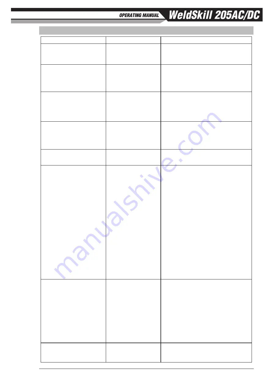
5.06  TIG (GTAW) Welding Problems

FAULT

CAUSE

REMEDY

1 Excessive bead build up or 

poor penetration or poor 

fusion at edges of weld.

Welding current is too 

low

Increase weld current and/or faulty joint 

preparation.

2 Weld bead too wide and 

flat or undercut at edges 

of weld or excessive burn 

through.

Welding current is too 

high

Decrease weld current.

3 Weld bead too small or 

insufficient penetration or 

ripples in bead are widely 

spaced apart.

Travel speed too fast

Reduce travel speed.

4 Weld bead too wide or 

excessive bead build up or 

excessive penetration in 

butt joint.

Travel speed too slow

Increase travel speed.

5 Uneven leg length in fillet 

joint

Wrong placement of 

filler rod

Re-position filler rod.

6 Electrode melts or oxidises 

when an arc is struck.

A Torch lead connected 

to positive welding 

terminal.

A Connect torch lead to negative welding 

terminal.

B No shielding gas 

flowing to welding 

region.

B Check the shielding gas lines for kinks 

or breaks and shielding gas cylinder 

contents.

C Torch is clogged with 

dust or dirt.

C Clean torch.

D Shielding gas hose is 

damaged.

D Replace shielding gas hose.

E Shielding gas regulator 

turned off.

E Turn On Shielding Gas and adjust 

Shielding Gas flow rate for the welding 

job. Refer to Table 5-7 on Page 5-10.

F The electrode is too 

small for the welding 

current.

F Increase electrode diameter or reduce the 

welding current.

7 Dirty weld pool

A Electrode contaminated 

by contact with work 

piece or filler rod 

material.

A Clean the electrode by grinding off the 

contaminates.

B Work piece surface has 

foreign material on it.

B Clean surface.

C Shielding gas 

contaminated with air.

C Check shielding gas lines for cuts and 

loose fitting or change shielding gas 

cylinder.

8 Poor weld finish

Inadequate shielding 

gas.

Increase shielding gas flow or check 

shielding gas line for shielding gas flow 

problems.

Содержание CIGWELD WeldSkill 205AC/DC

Страница 1: ...Version No AA Issue Date 15 04 2019 Manual No 0 5555 P N W1008205 OUTPUT CURRENT AC DC STICK ELECTRODE 4 0mm MAX WARRANTY 2 WARRANTY 3 205A HF...

Страница 2: ...ffort to bring you the best products we may make an improvement that does not get reflected in the manual If you are ever in doubt about what you see or read in this manual with the product you receiv...

Страница 3: ...www cigweld com au Copyright 2019 CIGWELD Pty Ltd All rights reserved Reproduction of this work in whole or in part without written permission of the publisher is prohibited The publisher does not ass...

Страница 4: ...hereof contained in this manual and accompanying labels and or inserts when installed operated maintained and repaired in accordance with the instructions provided This equipment must be checked perio...

Страница 5: ...EEA has been used in the design AS 60974 1 2006 Arc Welding Equipment Welding Power Sources IEC 60974 1 2000 MOD IEC 60974 10 2014 Arc Welding Equipment Part 10 Electromagnetic Compatibility EMC Requ...

Страница 6: ...02 Location 3 1 3 03 Ventilation 3 1 3 04 Mains Supply Voltage Requirements 3 1 3 05 High Frequency Introduction 3 1 3 06 High Frequency Interference 3 2 3 07 Generators 3 2 3 08 Extension Leads 3 2 3...

Страница 7: ...6 8 6 15 Arc Length 6 8 6 16 Rate of Travel 6 8 6 17 Making Welded Joints 6 8 6 18 Distortion 6 10 6 19 The Cause of Distortion 6 11 6 20 Overcoming Distortion Effects 6 12 6 21 Welding Problems 6 14...

Страница 8: ...This Page Intentionally Blank...

Страница 9: ...rical earth ground 11 Do not touch electrode while in contact with the work ground circuit 12 Use only well maintained equipment Repair or replace damaged parts at once 13 In confined spaces or damp l...

Страница 10: ...of Welding Current in Amps Minimum Shade Number of Filter s Manual Metal Arc Welding covered electrodes MMAW Less than or equal to 100 8 100 to 200 10 200 to 300 11 300 to 400 12 Greater than 400 13...

Страница 11: ...rike flam mable material 3 Remove all flammables within 35 ft 10 7 m of the welding arc If this is not possible tightly cover them with approved covers 4 Be alert that welding sparks and hot materials...

Страница 12: ...g AndThe Effects of Low Frequency Electric and Magnetic Fields The following is a quotation from the General Conclusions Section of the U S Congress Office of Technology Assessment Biological Effects...

Страница 13: ...as Association 1235 Jefferson Davis Highway Suite 501 Arlington VA 22202 Code for Safety in Welding and Cutting CSA Standard W117 2 from Canadian Standards Association Stan dards Sales 178 Rexdale Bou...

Страница 14: ...GENERAL INFORMATION 1 6 0 5555 This Page Intentionally Blank...

Страница 15: ...s Manual This Owners Manual only applies to the Part Numbers listed on page i To ensure safe operation read the entire manual including the chapter on safety instructions and warnings Throughout this...

Страница 16: ...Duty Cycle Percentage Amperage Voltage Hertz cycles sec Frequency Negative Positive Direct Current DC Protective Earth Ground Line Line Connection Auxiliary Power Receptacle Rating Auxiliary Power Ar...

Страница 17: ...ommended that such repairs be carried out by appropriately qualified persons approved by CIGWELD Advice in this regard can be obtained by contacting accredited CIGWELD Distributor This equipment or an...

Страница 18: ...cycle 90 amperes at 23 6 volts This means that it has been designed and built to provide the rated amperage 90A for 6 minutes i e arc welding time out of every 10 minute period 60 of 10 minutes is 6 m...

Страница 19: ...factor 8kW at 1 0 power factor Output Terminal Type Dinse Style 50 TIG GTAW Welding Output 40 C 10 min 205A 20 18 2V 120A 60 14 8V 95A 100 13 8V Open Circuit Voltage 63V STICK MMAW Welding Output 40...

Страница 20: ...s NOTE 4 CIGWELD reserves the right to change product performance and specifications without notice NOTE 5 If an extension lead is required to be used it is recommended to use a minimum size of 2 5mm2...

Страница 21: ...Torches pkt of 5 BG10N25 R Collet 3 2mm for 17 26 18 TIG Torches pkt of 5 BG10N30 R Collet Body 1 0mm for 17 26 18 TIG Torches pkt of 5 BG10N31 R Collet Body 1 6mm for 17 26 18 TIG Torches pkt of 5 BG...

Страница 22: ...4 WeldSkill Auto Darkening Welding Helmet Variable Shade 9 13 Oz Flag 454335 WeldSkill Auto Darkening Welding Helmet Variable Shade 9 13 Flaming Skull 454336 WeldSkill Auto Darkening Welding Helmet Va...

Страница 23: ...cy section of this machine has an output similar to a radio transmitter The machine should NOT be used in the vicinity of blasting operations due to the danger of premature firing 3 01 Environment The...

Страница 24: ...m Heavy Duty Extension Lead Longer extension leads may impact welding performance and operation 3 09 Short Circuit Protection While Welding To prolong the useful life of a TIG tungsten elec trode the...

Страница 25: ...equipment should be routinely maintained according to the manufacturer s recommendations All access and service doors and covers should be closed and properly fastened when the welding equip ment is...

Страница 26: ...iometer Wiper 8 Not Used Table 3 1 Description The CIGWELD Foot Control is a foot operated switch and potentiometer which starts and stops the welding process and controls welding current through oper...

Страница 27: ...he respective front panel control irrespective of the remote control device setting As an example if the output current on the power source front panel is set to 50 of the available current and the re...

Страница 28: ...INSTALLATION 3 6 0 5555 This page is left blank intentionally...

Страница 29: ...would vary according to the type of electrode in use The operator should use the welding current range values as a guide then finally adjust the current setting to suit the application 4 02 WeldSkill...

Страница 30: ...ote Control 5k ohm Potentiometers Maximum 6 Remote Control 5k ohm Potentiometers Minimum 7 Remote Control 5k ohm Potentiometer Wiper 8 Not used Table 4 1 8 Pin Interconnection Control Plug Configurati...

Страница 31: ...g the power source should remain ON such that the fan continues to operate allowing the unit to cool sufficiently If after 30 minutes with the fan running the Fault Indicator has not gone OFF then hav...

Страница 32: ...e To select and set Spot time first select Spot Mode on the Trigger and Spot Mode Control Button then either using the Multifunction Control Knob 11 or Back button increment until the Spot Time indica...

Страница 33: ...be able to control between 0 100 output 16 VRD ON OFF Indicator A VRD voltage reduction device is a hazard reducing device designed to reduce electric shock hazards present on the output of welding po...

Страница 34: ...ng Gas Inlet The Gas Inlet connection is used to supply the appropriate TIG welding gas to the unit Refer to Section 5 02 for TIG setup details Ensure that the shielding gas hose connection is suffici...

Страница 35: ...loose part 3 DO NOT remove the regulator flowmeter from a cylinder without first closing the cylinder valve and releasing gas in the regulator flowmeter high and low pressure chambers 4 DO NOT use th...

Страница 36: ...amage internal regulator parts 2 Since the regulator is a preset type no adjustments to the regulator are necessary Before opening the cylinder valve be sure that the flow adjusting valve is in a fing...

Страница 37: ...rrent control if applicable via the 8 pin socket located on the front of the Power Source The TIG torch will require a trigger switch to weld in TIG Mode D Connect the work lead to the positive weldin...

Страница 38: ...rgon Regulator Gas Hose Figure 5 3 Setup For TIG GTAW Welding 5 03 TIG Programming Modes CAUTION HF is present in allTIG modes This may cause damage to measuring equipment connected to the output of t...

Страница 39: ...sed to weld two thin plates together at a desired location by melting the top and bottom plates together to form a nugget between them The weld time is set by the Spot Time In TIG Welding modes once t...

Страница 40: ...ode 100 Amps AC TIG mode 50 Amps DC Pulse and AC Pulse TIG modes Peak Current This parameter sets the PEAK weld current when in DC or AC Pulse TIG mode Range 10 to 205 Amps 100 Amps DC Pulse and AC Pu...

Страница 41: ...and AC Pulse TIG modes AC Frequency This parameter operates in AC TIG mode or AC Pulse TIG mode and is used to set the frequency for the AC weld current Range 20 to 250 Hz 100 Hz Wave Balance This pa...

Страница 42: ...Balance 65 A 11223 Table 5 2 AC TIG Wave Balance 5 04 Factory Reset CAUTION AllWelding Parameters will be restored to the factory setting To restore to factory settings Press and hold the Multifunctio...

Страница 43: ...ce Can Be Any Commercial Metal Gas Cup Either Ceramic High lmpact or Water Cooled Metal Inert Gas Shields Electrode and Weld Puddle Tungsten Electrode Non Consumable Art A 09658_AC Figure 5 6 TIG Weld...

Страница 44: ...le 5 6 Base Metal Thickness DC Current for Mild Steel DC Current for Stainless Steel Tungsten Electrode Diameter Filler Rod Diameter if required Argon Gas Flow Rate Litres min Joint Type 0 040 1 0mm 3...

Страница 45: ...al A Connect torch lead to negative welding terminal B No shielding gas flowing to welding region B Check the shielding gas lines for kinks or breaks and shielding gas cylinder contents C Torch is clo...

Страница 46: ...Cigweld Tungsten Electrode Selection Chart C Shielding gas flow rate is too high C Select the right shielding gas flow rate for the welding job Refer to Table 5 7 on page 5 10 D Incorrect shielding g...

Страница 47: ...l If in doubt consult the electrode manufac turer Welding current flows from the power source via Dinse type terminals It is essential however that the male plug is inserted and turned securely to ach...

Страница 48: ...s the Process Selection button to select STICK mode Use the Multi Function Control to adjust the Parameter selected While welding the Multi Function Control directly controls the BASE CURRENT Adjust p...

Страница 49: ...nt fit up in certain situations with particular electrodes In general increasing the Arc Force control toward 100 maximum Arc Force allows greater penetration control to be achieved Range 0 to 100 30...

Страница 50: ...anised steels Excellent for vertical down fillet welding applications OK 53 16 Spezial 2 5mm 3 2mm 4 0mm 1 8 kg 1 6 kg 2 2 kg 53162534G1 53163234G0 53164044G0 Hydrogen Controlled type offering excepti...

Страница 51: ...d by using the correct electrodes pre heating using higher current settings using larger electrodes sizes short runs for larger electrode deposits or tempering in a furnace B Austenitic manganese stee...

Страница 52: ...rhead position butt weld Art A 07694 Figure 6 10 Overhead position fillet weld 6 11 Joint Preparations In many cases it will be possible to weld steel sections without any special preparation For heav...

Страница 53: ...the work either directly or through the work table For light gauge material always clamp the work lead directly to the job otherwise a poor circuit will probably result 6 13 The Welder Place yourself...

Страница 54: ...plate to form a bead The electrode is directed at the weld pool at about 20 from the vertical The rate of travel has to be adjusted so that a well formed bead is produced If the travel is too fast the...

Страница 55: ...the line of the fillet and about 45 from the vertical Some electrodes require to be sloped about 20 away from the perpendicular position to prevent slag from running ahead of the weld Refer to Figure...

Страница 56: ...gth of waste pipe Then tack this to the work bench or hold in a vice so that the specimen is positioned in the overhead position as shown in the sketch The electrode is held at 45 to the horizontal an...

Страница 57: ...te material is heated to a very high temperature and attempts to expand in all directions It is able to do this freely at right angles to the surface of the plate i e through the weld but when it atte...

Страница 58: ...C Restraint of Parts Forcible restraint of the components being welded is often used to prevent distortion Jigs positions and tack welds are methods employed with this in view D Presetting It is poss...

Страница 59: ...710_AB 1 Block Sequence The spaces between the welds are filled in when the welds are cool 2 3 Figure 6 26 Welding sequence Art A 07711_AB 4 3 2 1 Figure 6 27 Step back sequence Art A 07712 Figure 6 2...

Страница 60: ...left by failure of the weld metal to fill the root of the weld A Welding current is too low A Increase welding current B Electrode too large for joint B Use smaller diameter electrode C Insufficient g...

Страница 61: ...filled by the weld metal undercut A Welding current is too high A Reduce welding current B Welding arc is too long B Reduce the length of the welding arc C Angle of the electrode is incorrect C Electr...

Страница 62: ...trapped C If very bad chip or grind out irregularities D Lack of penetration with slag trapped beneath weld bead D Use smaller electrode with sufficient current to give adequate penetration Use suitab...

Страница 63: ...ended 7 02 Cleaning the Welding Power Source WARNING There are extremely dangerous voltage and power levels present inside this product Do not attempt to open or repair unless you are a qualified elec...

Страница 64: ...a good connection to the work piece 3 Fault Indicator is illuminated and unit will not commence welding when the torch trigger switch is depressed Duty cycle of power source has been exceeded Leave t...

Страница 65: ...006914 Gas Solenoid Assembly 6 W7006925 Front Panel 7 W7006915 Gas Outlet 8 W7006852 Socket Dinse 50mm2 9 W7006917 8 Pin Control Socket socket and pins only 10 W7006916 PCBA Display 11 W7006927 Displa...

Страница 66: ...O DESCRIPTION 1 W7005900 Trigger assembly for 26F torch 2 W7005901 Handle assembly for 26F torch 3 W7005902 Dinse 50mm for 26F torch 4 W7005903 Flex head for 26F torch 5 BGSAK2 Tig accessory Kit 6 UOA...

Страница 67: ...1 LED1 LED34 Absorption Circuit CN1 1 2 CN7 1 2 1 2 CN8 CN4 1 2 CN2 1 2 3 1 2 CN5 1 2 3 CN5 Absorption PCB CN2 1 2 CN3 1 2 CN6 1 2 3 CN4 3 2 1 CN6 3 2 1 CN1 1 2 CN3 3 2 1 1 2 H1 VR1 1 2 3 4 P2 M 0 Red...

Страница 68: ...APPENDIX A 2 0 5555 This Page Intentionally Blank...

Страница 69: ...ARE VOID IF REPLACEMENT PARTS OR ACCESSORIES ARE USED WHICH IN CIGWELD S SOLE JUDGEMENT MAY IMPAIR THE SAFETY OR PERFORMANCE OF ANY CIGWELD PRODUCT PURCHASER S RIGHTS UNDER THIS WARRANTY ARE VOID IF T...

Страница 70: ...cutting and Oxy fuel torches O rings fuses filters or other parts that fail due to normal wear Note No employee agent or representative of CIGWELD is authorized to change this warranty in any way or...

Страница 71: ...This Page Intentionally Blank...

Страница 72: ...08 Fax 61 3 9474 7488 cigweld com au Malaysia No 14 Jalan Teknologi 3 1 Selangor Science Park 1 Kota Damansara 47810 Petaling Jaya Malaysia Tel 60 3 6145 0995 Fax 60 3 6145 0585 Indonesia JI Pulogadun...

Отзывы: