ERL tesla lite Скачать руководство пользователя страница 257

Appendix E DNP3 Device Profile

D03283R01.10

TESLA LITE User Manual

Appendix E-9

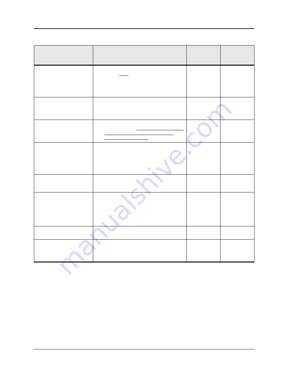
1.6 Fill Out The Following 

Items For Outstations 
Only

Capabilities

Current Value

If configurable, 
list methods

1.6.1

Timeout waiting for 
Application Confirm of 
solicited response 
message:

None

Fixed at 5,000 ms

Configurable, range _______ to _______ms

Configurable, selectable from ___,___,___ms

Configurable, other, describe______________

Variable, explain _______________________

5,000 ms

1.6.2

How often is time 
synchronization 
required from the 
master?

Never needs time

Within ______ seconds after IIN1.4 is set

Periodically every _______ seconds

1.6.3

Device Trouble Bit 
IIN1.6:

Never used

Reason for setting: Unable to access requested 
data or execute CROB, assuming a valid 
request has been received

1.6.4

File Handle Timeout:

Not applicable, files not supported

Fixed at______ ms

Configurable, range _______ to _______ms

Configurable, selectable from ___,___,___ms

Configurable, other, describe______________

Variable, explain _______________________

1.6.5

Event Buffer Overflow 
Behaviour:

Discard the oldest event 

Discard the newest event

Other, explain _________________________

1.6.6

Event Buffer 
Organization:

   •  Single buffer for the Object Groups 2 and 32, size 

200.

   •  Separate buffer for the Object Group 111, size 

100.

   •  Separate buffer for the Fault Locator events, size 

100.

1.6.7

Sends Multi-Fragment 
Responses:

Yes

No

1.6.8

DNP Command 
Settings preserved 
through a device reset:

Assign Class

Analog Deadbands

Data Set Prototypes

Data Set Descriptors

Not supported

Содержание tesla lite

Страница 1: ...TESLA LITE Power System Recorder User Manual Version 1 1 Rev 0 ...

Страница 2: ......

Страница 3: ...rising from the use of this documentation While all information presented is believed to be reliable and in accordance with accepted engineering practices ERLPhase makes no warranties as to the completeness of the information All trademarks used in association with B PRO B PRO Multi Busbar Multi Busbar Protection F PRO iTMU L PRO ProLogic S PRO T PRO TESLA I O Expansion Module TESLA Control Panel ...

Страница 4: ......

Страница 5: ...clarify the details of the equipment The manual uses a number of conventions to denote special information Example Describes Start Settings Control Panel Choose the Control Panel submenu in the Set tings submenu on the Start menu Right click Click the right mouse button Recordings Menu items and tabs are shown in italics service User input or keystrokes are shown in bold Text boxes similar to this...

Страница 6: ......

Страница 7: ...onnections 2 2 3 TESLA Control Panel Installation 3 1 Installing TESLA Control Panel 3 1 Installation on Windows XP and Windows 7 3 2 First Time Start Up 3 6 4 Communicating with the Recorder 4 1 Communication Ports 4 1 IRIG B Time Input 4 2 Communicating with the Recorder IED 4 2 Ethernet LAN Link 4 3 USB Link 4 6 Direct Serial Link 4 9 Modem Link 4 11 Modem LAN Gateway 4 14 Accessing SCADA Servi...

Страница 8: ...uration Files 8 1 Configuration Editor 8 4 Identification 8 5 TESLA Alarms 8 6 Channels and Triggers 8 7 Analog Input Channels 8 15 External Input Channels 8 19 Summation Channel 8 21 Sequence Component Channels 8 24 Impedance Channels 8 27 Watts and Vars Channels 8 30 Frequency Channels 8 33 Logic Functions 8 35 Fault Locator Functions 8 38 Power Factor Functions 8 40 Meter Groups 8 43 Trend Logg...

Страница 9: ...ing Channels for TESLA LITE Swing Recordings 10 77 COMTRADE Import 10 77 Print Options 10 79 11 Record Export Utility 11 1 COMTRADE Format 11 3 PTI Format 11 5 Excel CSV Format 11 7 12 Maintenance Menu and Error Handling 12 1 Maintenance Menu 12 1 Error Handling 12 5 Appendix A Specifications A 1 Appendix B TESLA LITE Hardware Description B 1 Appendix C Glossary C 1 Appendix D Modbus Functions D 1...

Страница 10: ......

Страница 11: ... User Manual ix Version Compatibility Please contact ERLPhase Customer Service for complete Revision History TESLA LITE Version Compatibility TESLA LITE Firmware Setting Version TESLA Control Panel v1 1 402 v2 7 v1 0 401 v1 4 ...

Страница 12: ......

Страница 13: ...ndows PC The CD ROM contains the following TESLA Control Panel Program for the recorder TESLA LITE Firmware Firmware and installation instructions TESLA LITE User Manual TESLA LITE manual in PDF format USB Driver To Install Software on your Computer Insert the CD ROM in your drive The CD ROM should open automatically If the CD ROM does not open automatically go to Windows Explorer and find the CD ...

Страница 14: ...er may be logged in as a Limited User as administrator privileges are not generally re quired for operation of the program The exception to this is the ability to com municate with TESLA LITE recorders through Modem LAN Gateway see If an internal modem was installed at the factory it will already be appropriately configured on page 4 13 Overview Once these steps are complete go to the First Time S...

Страница 15: ...includes RecordGraph a graph ical record display and analysis software tool An optional central station program RecordBase Central Station is available to automatically collect and store records from multiple recorders RecordBase provides fast network based access to collected records through distributed RecordBase View desktop clients 1 2 TESLA LITE Features Installation 19 rack mount format Smal...

Страница 16: ...imal Record Length for the dynamic swing recording is user config urable and is set in the Utilities Recording Trend recording for 45 user configurable channels for 15 days at sample in tervals from 10 seconds to one hour Calculated channels summations watts vars power factor positive nega tive and zero sequence components impedance fault location frequency harmonics and logic channels Record comp...

Страница 17: ...hout connecting to the recorder Record display shows record summaries with trigger event lists so that a pre liminary evaluation can be made before the record is transferred Real time metering display shows all input and calculated quantities in user customizable layouts Analysis Tools Recorder configuration and relevant event information is embedded in each record Record graphics provide a flexib...

Страница 18: ...TCP IP communication protocol used to communicate with Control Panel and RecordBase software SCADA Supervisory Control and Data Acquisition Systems protocols DNP3 and Modbus DNP3 over Ethernet is supported 1 3 Front Panel Figure 1 1 Front Panel USB port Table 1 1 Port Numbers for TESLA LITE 450 USB port 401 100BASE T 400 internal modem 403 IRIG B 404 RS 232 SCADA 405 RS 232 User Interface serial o...

Страница 19: ...0 117 200 235 and 300 321 External Inputs Ports 322 335 Output Contacts Ports 536 537 Power Supply 43 to 275 Vdc 90 to 265 Vac Port 538 Chassis Ground Port 400 Internal Modem option Port 401 100 1000 BASE T Ethernet Network Port 402 Disabled Port 403 IRIG B External Clock modulated or unmodulated Port 404 EIA 232 SCADA Communication DNP 3 and Modbus Port 405 EIA 232 Serial Connection for PC or an ...

Страница 20: ......

Страница 21: ...tarts its initialization process See Installing TESLA Control Panel on page 3 1 for the start up process details The use of an external surge protection device is required to pass the surge im munity requirements of IEC EN 60255 22 5 Criterion A ERLPhase recom mends either of the following for this function ERLPhase p n 107898 Manufacturer Phoenix Contact Ltd Manufacturer s p n 2858357 PT 2 PE S 2...

Страница 22: ...ser configurable 4 User configurable 5 User configurable 6 Cross trigger 7 Recorder function The cross trigger contact is used to initiate recording on another recorder when this unit triggers When activated the cross trigger contacts close for 0 10 sec onds regardless of the duration of the triggering condition This ensures that the cross trigger function does not become blocked by a continuous t...

Страница 23: ...cted the LED is turned off The LED state corresponds directly with the Failure Contact IRIG B Functional Green LED that is active when a valid external time synchronizing sig nal is detected on the IRIG B port Recorder Triggered Green LED that is active while the recorder is in the process of creat ing a record Records Stored Green LED that turns on when there are records stored in the recorder s ...

Страница 24: ......

Страница 25: ...cate with TESLA LITE recorders through Modem LAN Gateway see Modem LAN Gateway on page 4 14 Overview Instructions for installing TESLA Control Panel and configuring Windows for its use are covered in the following sections Separate instructions for each ver sion of Windows Operating System are provided for the above steps Use the one that is appropriate for your computer The procedure has the foll...

Страница 26: ...on trol Panel 5 When the installation is complete a TESLA Control Panel icon is placed on your desktop Use the icon to launch Control Panel If you prefer you can start Control Panel through Windows Start menu Start Programs ERLPhase TESLA Control Panel Step 2 Installing Null Modem Driver Software A virtual software modem called a Null Modem must be set up for direct se rial cable communication bet...

Страница 27: ...directory Program Files x86 is used for Windows 7 64 bit operating systems instead of Program Files Select OK This is the default location for TESLA Control Panel If you selected a different location to install TESLA Control Panel you will find the Null Modem driver Null_Mdm Inf in that directory Step 1 Start Settings Control Panel Step 2 Double click Modems icon Step 3 Add Step 4 Select Don t det...

Страница 28: ...3 2 Browse for Null_Mdm Inf 6 Select the ERLPhase Null Modem driver and select Next 7 Select the serial port you wish to use You are setting up a serial port to be used for a direct cable connection to a TESLA Typically COM1 or COM2 are available on a PC for this purpose Select Next ...

Страница 29: ...elect Serial Port In Windows XP you may get a message stating that the Null Modem has not passed Windows Logo testing and asking Do you want to continue the installation Select Continue Anyway to continue 8 Select Finish and close the Phone and Modem Options and Control Panel dialog boxes ...

Страница 30: ... Data although you may change this later by using the File Data Loca tion command from the Main Menu Program Files x86 for Windows 7 64 bit operating systems Figure 3 4 Data Location When you change the data location previously configured IEDs will not be affected Only newly created IEDs will use the new data loca tion To edit the data location of existing IEDs use the Main Menu Edit button Note t...

Страница 31: ... stop bit Rear Panel 400 RJ11 receptacle Internal modem interface Default Baud rate 38 400 N81 no parity 8 data bits 1 stop bit Rear Panel 401 RJ 45 receptacle 100BASE T Ethernet interface Same subnet as front panel port 401 Used for user interface access or DNP SCADA access through Ethernet LAN Rear Panel 403 BNC receptacle IRIG B Interface Modulated or un modulated 330 ohm impedance Rear Panel 4...

Страница 32: ...recorder You can enable or disable the IEEE 1344 extension in the terminal mode set tings Utilities Setup Time The enabled mode receives the year from the IRIG B signal Disable this setting if the available IRIG B signal has no year extension 4 3 Communicating with the Recorder IED You can connect to the recorder to access its user interface and SCADA ser vices by Front USB 2 0 interface user inte...

Страница 33: ...s not suitable it may be modified using the relay s Maintenance Menu see Maintenance Menu and Error Handling on page 12 1 Modify the Default Gateway and Network Mask if necessary The Default Gateway may need to be changed if the recorder and the control panel or RecordBase are on different but connected networks The default setting is No Default Gateway The Network Mask may need to be changed if t...

Страница 34: ... target recorder from the Select IED list in TESLA Control Pan el s Main Menu If there is not already an entry for this recorder create one using the Add New button Figure 4 2 Edit IED The method of communication with the recorder is specified as part of its IED definition Use the Edit button to view or change this informa tion Ensure the Network Link option is selected and the recorder s IP addre...

Страница 35: ...tions see Working with TESLA Control Pan el on page 5 1 4 Initiate the connection by selecting the Connect button A dialog box will appear to show connection progress The connection state and the current IED you are connected to is shown on the Windows status bar Figure 4 3 Connect Button Dialog Box ...

Страница 36: ...the window Welcome to the Found New Hardware Wizard Can Windows connect to Windows Update to search for software Check the option No not this time In the window This wizard helps you install software for ERLPhase 4000 Series Device What do you want the wizard to do Check the option Install from a list or specific location Advanced In the window Please choose your search and installation options Se...

Страница 37: ...mall icons view go to Start Control Panel Device Manager Ports Look for the port number associated to this device ERLPhase 4000 Series Device Look for a COM where can be 1 2 3 etc Leave the default settings for this port It is recommended to restart the PC after the USB driver installation The default baud rate for the recorder USB Port 450 is 115200 however to double check it login to the recorde...

Страница 38: ...ect button A dialog box will appear to show connection progress The connection state and the current IED you are connected to is shown on the Windows status bar at the bottom of the screen Figure 4 5 Status Bar If the connection fails check the following The communication parameters are the same on both ends see Step 1 above The correct serial port has been selected on your computer Some newer lap...

Страница 39: ...ation parameters Port 405 is fixed at 8 data bits no parity and 1 stop bit and has a default baud rates of 38 400 bauds 2 Choose the target recorder from the Select IED list in TESLA Control Pan el s Main Menu If there is not already an entry for this recorder create one using the Add New button The method of communication with the recorder is specified as part of its IED definition Use the Edit b...

Страница 40: ...atus Bar If the connection fails check the following The communication parameters are the same on both ends see Step 1 above The correct serial port has been selected on your computer Status Bar shows TESLA Control Panel software is connected to the recorder and the name of the Current IED ...

Страница 41: ...nd cabling information see Communication Port De tails on page 4 20 If the unit has an internal modem an external modem will not work 2 Connect the modem to an analog telephone line or switch and turn it on A standard telephone cable with an RJ 11 connector is used 3 Configure the recorder s Port 405 to work with the modem Port 405 settings are accessed through the recorder s standard user in terf...

Страница 42: ...red by your modem The factory default for this field is M1 for external modems These default values are all that are re quired for most modems f Save your changes close the Utilities tab and disconnect TESLA Control Panel Setup 1 Configure your computer to work with its modem Refer to your computer and modem documentation 2 Choose the target recorder from the Select IED list in TESLA Control Pan e...

Страница 43: ...dem Link Internal You can access the recorder s user interface through a telephone link between the relay and your computer using an optional internal modem Port 400 if installed Connect the recorder s Port 400 to an analog telephone line or switch using a standard RJ 11 connector Internal modem configuration is done the same way as for external modem Modem initialization string is M1 for internal...

Страница 44: ... master recorder with an internal or external modem see External Modem on page 4 11 or Inter nal Modem on page 4 13 3 Enable TCP packets forwarding on the master recorder for details see Main tenance Maintenance Menu Commands on page 12 3 4 Set up TESLA Control Panel to communicate with the master recorder via the PC s modem and create and configure an appropriate IED Definition for it see Externa...

Страница 45: ...can be used to connect to an RS 485 network For port pin out and cabling information see Communication Port Details on page 4 20 Ethernet Connection The DNP protocol can also be available over Ethernet using TCP or UDP A standard 100BASET Ethernet cable is required The Ethernet port can support DNP SCADA and user interface access via TES LA Control Panel at the same time For details on setting the...

Страница 46: ...fies the time in which the recorder expects a response from the SCADA master to primary frame messages If a response is not received in this time the recorder will re transmit the message Configuration default timeout is 1000 ms per DNP3 Technical Bulletin 9804 002 This document is available from the DNP3 User s Group www dnp org For UDP and TCP modes the timeout is not settable and is automatical...

Страница 47: ...s Protocol The data points available for Modbus SCADA interface are fixed and are not selectable by the user Complete details regarding the Modbus protocol emu lation and data point lists can be found in Modbus Functions on page Appendix D 1 Figure 4 12 Communications Setup In Control Panel for Modbus ...

Страница 48: ...elay An external RS 232 to RS 485 converter can be used to connect the relay to an RS 485 network Network DNP communications can be utilized via physical LAN Port 401 Port 401 is available as a pair of RJ 45 ports one on the front of the recorder and one on the rear DNP communications can be used with multiple masters when it is utilized with TCP The data points available for DNP SCADA interface a...

Страница 49: ...ta Diagnostics Protocol monitor utilities are available to assist in resolving SCADA commu nication difficulties such as incompatible baud rate or addressing The utilities can be accessed through the Maintenance user interface Maintenance Menu and Error Handling on page 12 1 Figure 4 14 HyperTerminal ...

Страница 50: ...heral software tools and de vices using the ERLPhase registered IANA Port 7631 Previous firmware ver sions configured for Port 2000 operation will be altered during the TESLA LITE firmware update process to use Port 7631 Notes IED is DCE PC is DTE Pins 1 and 6 are tied together internal to the IED Table 4 3 TESLA Recorder Serial Ports Port Location Function 405 Rear Panel Serial port for connectio...

Страница 51: ...al to the IED Table 4 5 Cable Pin Connections Male DB 9 Cable End for IED Port Female DB 9 Cable End for Computer Port Pin on Cable Pin on Cable 1 1 2 2 3 3 4 4 5 5 6 6 7 7 8 8 9 9 Table 4 6 Signal name connections to pins on Modem Adapter Signal Name Direction Modem IED Pin on the Modem Adapter DCD 1 RxD 2 TxD 3 DTR 4 Common 5 DSR 6 RTS 7 CTS 8 No connection 9 ...

Страница 52: ...Listening port on System Manager TESLA connects to this port 7631 Listening ports on TESLA RecordBase Central Station and TESLA Control Panel connection ports Configurable through Maintenance Menu 20 21 FTP 23 Telnet 4712 TCP or Udp Default PMU port can be modified by the user TESLA 3000 and TESLA 4000 20000 TCP or UDP Default DNP3 can be modified by the user TESLA 2000 3000 and 4000 ...

Страница 53: ...LA Demo Unit It contains sample records and configuration files and is configured for network connection with an evaluation unit Selecting a Recorder Workspace To work with a particular recorder select it from the Select IED box on the Main Menu tab If you are already connected to an IED you will not be able to select a different IED until you disconnect Figure 5 1 Selecting a Recorder Workspace A...

Страница 54: ...unication parameters specified for this IED TESLA Control Panel assumes that the recorder it is communicating with is the one identified as the Current IED Forcing a connection with a different re corder i e moving the serial cable without telling Control Panel to discon nect can cause the records and configuration files of that recorder to be mixed with those of the Current IED The name of the Cu...

Страница 55: ... in Figure 5 2 Recorder Workspace Definition and the settings are described in the following table Figure 5 2 Recorder Workspace Definition Table 5 1 IED Workspace Settings IED Definition IED Name The IED Name is the name you assign to this recorder s workspace It appears in the IED selection and the Current IED display at the bot tom of the TESLA Control Panel window We recommend that you use the...

Страница 56: ...one link Network Link Connect to this recorder via a TCP IP network Connect Through IED Connect to this recorder through another recorder that is providing a modem Lan gateway An IED Definition for the selected recorder must already exist For details on setting up a modem Lan Gateway If an internal modem was installed at the factory it will already be appropriately configured on page 4 13 Folder P...

Страница 57: ...on files without being connected to the unit Online Connected In Online mode you are connected to the recorder and have access to both local and remote data and functions Records both local and on the recorder Event log Metering realtime readings of input and calculated channels Channel and trigger configurations the one presently active in the recorder and any saved ones you may have created Setu...

Страница 58: ...Utilities and Configuration are activated by a double click You can optimize the screen space between the tree and the working area to create a larger working area Some screens have a Hide Tree button to maxi mize the working area Working Area The Working Area on the right pane of the display represents the main working area of each section of the TESLA Control Panel Control Tabs The Control Tabs ...

Страница 59: ...lay Standard Metering Screens The Metering display provides tabs at the bottom to select among multiple dis play screens The first two tabs Analogs and Digitals are the default tabs and present the readings from the analog inputs and external inputs User Defined Metering Screens You can define an additional ten user defined metering screens Setup of these additional screens is part of the recorder...

Страница 60: ...eze The Freeze button provides a way to temporarily stop the update of the display It can be used to ensure a synchronized set of readings for documentation pur poses The metering display can be exported to another program using Win dows built in Alt PrintScreen key and standard paste functions Phase angle readings displayed in meter groups are based on the configured Phase Angle Reference Channel...

Страница 61: ...gth and mode settings Time display and settings Analog input calibration Central Station trigger and record notification Passwords Figure 7 1 Recorder Setup Utilities The setup parameters are accessed through the Utilities tab on TES LA Control Panel You must be communicating with the IED for the Utilities tab to be available For details on connecting to the recorder using TESLA Control Panel soft...

Страница 62: ... the unit It is part of the name given to records produced by the unit to identify their origin By convention this name should be the same as the IED Name assigned to the recorder and recorder s workspace The name must not contain the following or any other character not valid for a Windows file name IED Firmware Version Read only field that displays the firmware version of the currently connected...

Страница 63: ...Communication Ports Communication Version Read only field that displays the version of the communications pro tocol used by the currently connected TESLA unit System Frequency Read only field that displays the assumed power system frequency of the recorder This is a factory setting Station Station Name User defined for your reference only Station Number User defined for your reference only Locatio...

Страница 64: ... or a terminal program to access the Maintenance Menu External Modem Port 405 can be used to connect to an exter nal modem through a serial link Internal Modem Enables a modem connection through the recorder s rear panel RJ 11 Internal Modem Port Requires that the recorder has the internal modem option installed The internal modem can be disabled through the Maintenance Menu Baud Rate Sets the bau...

Страница 65: ...th modes are available for High Speed Recording only Edge Recording is available for Low Speed Recording Edge Mode Figure 7 4 Recorder Setup Utilities Edge Recording In Edge Recording the rising edge of the trigger is used to create a record that has a set amount of pre trigger data and a set amount of post trigger This is known as a normal length record If another trigger is processed while the r...

Страница 66: ... combined with the first trigger using a logical OR operation as long as it is not near to the maximum record length limit If the trigger is processed near the end of the record a new overlapping record will be created instead of combining the triggers Records with com bined High Speed and Low Speed data can only be combined during the High Speed data capture portion of the record Duration Recordi...

Страница 67: ...or mul tiple triggers the Maximum record Length must be larger than the Normal Record Duration Mode The maximum length of the record including pre trig ger trigger and post trigger Low Speed Recording Sample Rate Samples at 50 or 60 samples second 1 sample cycle producing record lengths of a few minutes to capture slower system dynamic swings The sample rate for low speed recording is based on the...

Страница 68: ...larm contact assigned to this is displayed as a read only value It s set as part of the recorder s configuration see TESLA Alarms on page 8 6 Trend Accumulation Mode Selects whether to overwrite the oldest trend data when the 15 day storage limit has been reached or to stop trend The Storage Alarm can be used in conjunction with the Stop setting to provide notifica tion in advance of the full cond...

Страница 69: ...IRIG B time sig nal to the recorder is sending local time the recorder converts it to UTC internally The time displayed in the Time Control screen above is determined by the ad jacent time display settings The recorder will automatically convert from its internal UTC time as required The Recorder Time Zone Setting determines the offset between Local time and UTC DST will automatically add 1 hour t...

Страница 70: ...define the format of the incoming time if IEEE 1344 data is not available Use IEEE 1344 If Present If Use IEEE 1344 if Present is checked and the source clock generates IEEE 1344 data the recorder Uses the time zone offset from the IEEE 1344 data embedded in the IRIG B time signal Reads the IEEE 1344 data to determine the mode of the incoming IRIG signal UTC Local Local with DST Otherwise the reco...

Страница 71: ...anual 7 11 7 5 Analog Input Calibration The Calibration Utility provides a means of calibrating the recorder s analog input channels It is accessed through the TESLA Control Panel s Utilities tab as Analog Input Calibration Figure 7 7 Analog Input Calibration ...

Страница 72: ...as not yet been con figured only Calibrate Offset will be displayed 4 Under the Offset and Gain columns the line of the channel being calibrated OK or No will be displayed see Analog Input Calibration on page 7 11 5 Repeat for all other channels being used 6 Use the Save button to load the new calibration to the recorder Out of Range An error message is displayed if the applied signal as seen by t...

Страница 73: ...c Record Transfer You can control which records are automatically transferred to the RecordBase Central Station by specifying the required record priority The setting ranges from 0 all records to 3 highest priority only and provides an option to dis able automatic record transfers completely Record priority is determined by the highest priority trigger included in the re cord Trigger priority is s...

Страница 74: ...tion Retry Attempts These rules are applied when the TESLA recorder fails to establish communication with RecordBase Central Station i e if the phone line is busy or if the network is down Maximum Attempts When the TESLA recorder fails to establish contact with RecordBase central station this is the maximum number of attempts it will make before giving up Delay Between Attempts Specifies the delay...

Страница 75: ...h the Passwords tab of TESLA Con trol Panel s Utilities screen You have the option of explicitly disabling the password protection for each access level Leaving the VIEW access level password disabled for example will allow free use of the TESLA LITE for read only operation The Password tab can only be accessed when connected via direct serial link through the recorder s service port Port 450 This...

Страница 76: ...Log VIEW Events Display Event Log VIEW Erase Event Log CHANGE Metering Metering Display VIEW Utilities Display Unit Identification VIEW Set Unit Identification CHANGE Display Communication Settings VIEW Set Communication Settings CHANGE Display Recording Settings VIEW Set Recording Settings CHANGE Display Time Settings VIEW Set Time Settings CHANGE Display Calibration VIEW Save Calibration Changes...

Страница 77: ...01 10 TESLA LITE User Manual 7 17 Edit Local Configuration None Rename Local Configuration None Import Local Configuration None Save as Local Configuration None Copy from other IED None New Configuration None Table 7 6 Setting Passwords ...

Страница 78: ......

Страница 79: ...e memory through the commu nications link 8 1 Managing Configuration Files TESLA Control Panel s Configuration Manager creates and manages config uration files and handles transfer to and from the recorder To open the Con figuration Manager screen double click the Configuration line in the left pane of the Main Menu screen The configurations shown in the Configuration Manager screen are specific t...

Страница 80: ...der This gives you a quick way to make changes on the fly You can also transfer the recorder s present configuration to a saved file in Control Panel using the Get from IED button When transferred the configu ration appears in the Saved Settings list Saved Configuration Files Figure 8 3 Saved Configurations Saved configuration files are shown under the Saved Settings heading in the list Control Pa...

Страница 81: ...ate a new configuration file New configuration files are compatible with the latest Setting Version by default The Setting Version can be changed if desired to create new configuration files for older recorders The fixed information in the Device Configuration screen is derived from the IED Definition Adding Editing a Recorder Workspace Definition on page 5 3 It is recommended that you maintain a ...

Страница 82: ...n item in the tree shifts the large right pane view to the appropriate topic Double clicking on a tree branch in the left pane that has a small to its left or selecting on the itself expands or collapses the tree Right Click Menu A right click in the editor provides you with options appropriate to your pres ent context For example you can create a new element by selecting the appro priate channel ...

Страница 83: ... see TESLA LITE Configuration Edi tor on page 8 4 Changing the setting automatically converts the configura tion file to the selected Settings Version If the conversion results in the loss of settings from the file i e the target version does not support functions which were enabled in the original a list of the affected settings is displayed and you have the choice of cancelling the conversion or...

Страница 84: ...epetitive triggers The chatter limit settings specify the time window Chatter Detection Window in which the chatter detector works The detector limits the number of triggers that can occur on the same channel and of the same trigger type within the window Four External Input triggers and two analog or calculated channel triggers are allowed in the window If this number is exceeded the trigger is a...

Страница 85: ...ission line named 1 you can define an ele ment and name it Line 1 The channels associated with that element might then be Line 1 Va Line 1 Vb Line 1 Vc Line 1 Ia Line 1 Ib Line 1 Ic External digital inputs can also be reasonably associated with the Line 1 Line 1 EI BRKR1_a Line 1EI 21N_Trip Calculated channels fit the model as well Line 1 W V watts and vars Line 1 Iseq current channel sequence com...

Страница 86: ...hase A voltage Ic Phase C current In Neutral current Vac Generic AC voltage dc dc voltage or current EI External inputs Vseq Sequence component set pos neg zero VaSum Summation of Phase A voltages W V Watts vars set PF Power factor Z1 Impedance Logic Logic function FLoc Fault locator Frequency Frequency one per channel group Description optional 12 chars Often the combination of the Element Name a...

Страница 87: ... names you create In the following figure Element Line 1 has been expanded to show some of the channels associated with it such as Va Figure 8 5 Element Tree View Channel View The Channel Tree View displays the same configuration organized by channel type You can use this view to gain an overview of channel usage Although you can chose to work in either view the Element View is recommended for mos...

Страница 88: ... last row of the display shows the channels and functions that are unassigned and available Phase Angle Reference Channel The Element Overview screen displayed by selecting Channel Group 1 in the Navigation tree is where you select the analog input channel to be used as the reference channel for angle measure ments All channels use the same reference to provide relative angle calculations Typicall...

Страница 89: ...on tree For example selecting Analog Inputs displays a table of all defined analog channels Figure 8 8 Channel Overview Screen The column width can be adjusted on the overview tables to optimize the lay out for the particular configuration Channel settings can be edited in the Channel Overview display pro viding an alternate way to enter channel settings that helps maintain consistency between cha...

Страница 90: ...guration is displayed on an individual channel basis The settings for each channel can be displayed in individual screens by select ing the specific channel in the Navigation Each channel type has its own con figuration screen with parameters appropriate for its type Figure 8 9 Individual Channel Configuration Screen ...

Страница 91: ...Channel Channels can be created in either the Element Tree view or the Channel Tree View Element and Channel Tree Views on page 8 9 To create a new channel in the Element Tree view 1 Select the desired element in the tree 2 Right click and select the desired channel type If appropriate choose the type that matches the input you are monitoring e g Va For an ac signal that has no specific phase desi...

Страница 92: ...lose the screen you are asked to save the configuration to the recorder Select Save to Recorder Figure 8 11 Adding Analog Input Channels from the Element Tree Deleting a Channel To remove an channel from the tree select it and press the Del key or right click and select the appropriate Delete entry from the shortcut menu Step 1 Select Analog Input Step 2 Right click and select New Analog Input Ste...

Страница 93: ...gh low magnitude Negative and positive rate of change Single harmonic magnitude THD magnitude Sag and swell To prevent multiple triggers on threshold conditions an hysteresis of 2 of setting is applied to magnitude triggers Recording High Speed records the samples generated from the A D converters at 96 sam ples per cycle Low Speed records the calculated phasors at a rate of one phasor per cycle N...

Страница 94: ... nating the need for the optional Description field e g Line 1 Va uniquely defines the channel Initially set when the channel was cre ated the Type can be changed to refer to a different phase as needed Description Optional field 12 characters Provides an additional description of the channel that forms part of the channel name Use if Element Name and channel Type do not sufficiently identify the ...

Страница 95: ...ls only See sag and swell detector details below Limit Specifies the trigger levels for the magnitude single harmonic THD sag and swell triggers Specifies the magnitude portion of the rate for rate of change triggers Delay Specifies how long the trigger condition must be present before a trig ger is declared Magnitude and Rate of Change triggers 0 to 1 200 seconds in half cycle increments Single h...

Страница 96: ...nd Swell detectors The definition of a Sag or Swell depends on a Nominal Level of voltage The Sag and Swell thresholds are expressed as a percentage of the Nominal Level The Sag threshold is configurable between 50 and 90 of Nominal The minimum Sag level is fixed at 10 of Nominal The Swell threshold is config urable between 110 and 150 of Nominal The maximum Swell level is fixed at 180 of Nominal ...

Страница 97: ...onsidered valid for triggering pur poses Triggers Active state Inactive state Recording Records the state of all external input channels at the selected high speed sam ple rate The input filter is not applied to the recorded data all state changes are included in the records Number of Channels Up to 38 External Input Channels can be defined one for each physical input Types EI Settings Figure 8 14...

Страница 98: ...s on and off Maximum 8 characters Trigger Actions Enable Enables or disables the associated trigger A trigger can be disabled without altering the rest of its settings Fault Initiates a fault high speed recording when triggered Swing Initiates a swing low speed recording when triggered If both Fault and Swing are enabled the recorder will attempt to cre ate a combined record Log Logs a message in ...

Страница 99: ... channel before the addition Triggers High low magnitude Negative and positive rate of change To prevent multiple triggers on threshold conditions an hysteresis of 2 of setting is applied to magnitude triggers Recording High Speed generates a channel that is the sum of the individual data samples with the Scale Factor applied A high speed channel is not generated if a non zero Angle Offset has bee...

Страница 100: ...en the channel was cre ated the Type can be changed to refer to a different phase as needed Description Optional field 12 characters Provides an additional description of the channel that forms part of the channel name Use if Element Name and channel Type do not sufficiently identify the channel Channel Grouping and Naming on page 8 7 Summation Index Identifies the summation channel Unlike the ana...

Страница 101: ...e increments Trigger Actions Enable Enables or disables the associated trigger A trigger can be disabled without altering the rest of its settings Fault Initiates a fault high speed recording when triggered Swing Initiates a swing low speed recording when triggered If both Fault and Swing are enabled the recorder will attempt to cre ate a combined record Log Logs a message in the Event Log when tr...

Страница 102: ...ents Triggers Positive sequence high and low magnitude Positive sequence negative and positive rate of change Negative sequence high magnitude Zero sequence high magnitude To prevent multiple triggers on threshold conditions an hysteresis of 2 of setting is applied to magnitude triggers Recording High Speed Positive negative and zero sequence values at a rate of eight val ues per cycle regardless ...

Страница 103: ...tional field 12 characters Provides an additional description of the channel that forms part of the channel name Use if Element Name and channel Type do not sufficiently identify the channel Channel Grouping and Naming on page 8 7 Sequence Index Identifies the Sequence Component channel Unlike the analog and external input channels this is not associated with a hardware input but simply identifies...

Страница 104: ...d the recorder will attempt to cre ate a combined record Log Logs a message in the Event Log when triggered Notify Contacts the RecordBase Central Station when triggered Can be used to initiate wide area swing recordings and or automated record transfer Notify on page 7 13 Cross Trigger Activates the cross trigger contact 6 to trigger another device Priority Specifies the priority to be assigned t...

Страница 105: ...e Calculation The impedance calculation continuously recalculates the apparent impedance from the selected voltage and current signals then subtracts an earlier calculat ed value determined by the Rate of Change Interval setting The impedance trigger operates if the difference is between the Minimum Change and Maximum Change settings and the calculated impedance is within Circle Radius of the orig...

Страница 106: ...ut sim ply identifies which of the internal virtual impedance channels will be used You can select any available channel without restriction If the only option is undefined you have already used all available channels Voltage Input Cur rent Input Identifies the channels to be used to create the impedance If you select analog or summation channels as inputs the impedance chan nel calculates single ...

Страница 107: ... Logs a message in the Event Log when triggered Notify Contacts the RecordBase Central Station when triggered Can be used to initiate wide area swing recordings and or automated record transfer Notify on page 7 13 Cross Trigger Activates the cross trigger contact 6 to trigger another device Priority Specifies the priority to be assigned to records created by this trigger The priority is used to de...

Страница 108: ...atts positive and negative rate of change 2 Vars high and low level Vars positive and negative rate of change Dual triggers for Watts allows fault and swing recordings to be triggered by different settings e g Rate of Change Interval if desired To prevent multiple triggers on threshold conditions an hysteresis of 2 of setting is applied to magnitude triggers Recording High Speed Watt and Var value...

Страница 109: ...elect any available channel without restriction If the only option is undefined you have already used all available channels Voltage Input Identifies the voltage channels to be used to create the watts and vars These can be either analog input channels summations or posi tive sequences If you select analog or summation channels as inputs single phase watts and vars will be calculated if you select...

Страница 110: ...abled the recorder will attempt to cre ate a combined record Log Logs a message in the Event Log when triggered Notify Contacts the RecordBase Central Station when triggered Can be used to initiate wide area swing recordings and or automated record transfer Notify on page 7 13 Cross Trigger Activates the cross trigger contact 6 to trigger another device Priority Specifies the priority to be assign...

Страница 111: ...ndow to improve resolu tion and accuracy The frequency measurement operates in a band that is ap proximately 15 of the nominal frequency Triggers High low magnitude Negative and positive rate of change To prevent multiple triggers on threshold conditions the frequency magnitude triggers have a fixed 0 02 Hz hysteresis Recording Low Speed Frequency measurements at a rate of one value per cycle Numb...

Страница 112: ...agnitude limit is 7 6 x nominal frequency low magnitude limit is 5 6 x nominal frequency Delay Specifies how long the trigger condition must be present before a trig ger is declared 0 0333 2 cycles to 1 200 seconds in half cycle incre ments Trigger Actions Enable Enables or disables the associated trigger A trigger can be disabled without altering the rest of its settings Fault Initiates a fault h...

Страница 113: ...s Active state Inactive state Recording Logic Functions are not recorded Number of Channels 15 Logic Functions are available Types Logic Notes The output of the Logic functions is available to the metering display SCADA and the long term trending function Priority Specifies the priority to be assigned to records created by this trigger The priority is used to determine Central Station notification...

Страница 114: ...ic functions require the input logic to have a lower Logic Function Index If the only option is undefined you have already used all available channels Inputs 1 5 Selects the source of the input state for each stage of the boolean cal culation External Input Channels trigger detectors from other chan nels and previously defined Logic Functions are available Inversion Blocks Allows the input state t...

Страница 115: ...page 7 13 Cross Trigger Activates the cross trigger contact 6 to trigger another device Priority Specifies the priority to be assigned to records created by this trigger The priority is used to determine Central Station notification 1 3 3 is the highest priority Notify on page 7 13 Alarm Contact Specifies a rear panel contact to be closed when triggered Contacts are closed momentarily for one seco...

Страница 116: ...ator assesses the distance to fault using the user supplied line parameters If one or more of the imped ances is consistent with a fault on the line fault identification e g B G and location information is generated in the form of an event message Triggers N A Recording Fault Locator Functions are not recorded Number of Channels 5 Fault Locator Functions are available Types FLoc Notes When a Fault...

Страница 117: ...tional field 12 characters Provides an additional description of the channel that forms part of the channel name Use if Element Name and channel Type do not sufficiently identify the channel Ref Channel Grouping and Naming on page 8 7 Fault Locator Index Identifies the Fault Location function You can select any available function If the only option is undefined you have already used all available ...

Страница 118: ...s and volt amps values computed by its input channel and operates when the power factor is less than a user specified threshold Separate detectors allow separate thresholds for lag ging inductive and leading capacitive power factors To reduce the inci dence of nuisance operations you may specify a minimum volt amps setting Triggers Inductive power factor Low magnitude Capacitive power factor Low m...

Страница 119: ...ing on page 8 7 PF Detector Index Identifies the Power Factor funtion You can select any available fun tion If the only option is undefined you have already used all availa ble channels Watts Vars function to monitor Specifies which Watts Vars channel to use as input Must be previ ously defined Trigger Settings Disable detector if VA less than Allows the trigger to be supervised by a minimum VA le...

Страница 120: ...e 7 13 Cross Trigger Activates the cross trigger contact 6 to trigger another device Priority Specifies the priority to be assigned to records created by this trigger The priority is used to determine Central Station notification 1 3 3 is the highest priority Notify on page 7 13 Alarm Contact Specifies a rear panel contact to be closed when triggered Contacts are closed momentarily for one second ...

Страница 121: ...displays for analog and external input chan nels You may add additional displays containing any set of channels orga nized as you wish 1 To create a meter group right click on the Meter Groups entry in the Con figuration menu 2 Select Add Meter Group A New Meter Group line appears and the New Meter Group text is selected 3 Type the Meter Group name then Enter The text you type replaces the New Met...

Страница 122: ...ved from the normal circular overwrite of the Event Log The trend log accumulates data for up to 15 days When it is full it can either be set to automatically overwrite the oldest data or to stop logging A near full alarm function is available The accumulation settings are defined in the recorder s Utilities menu see Recording Control Settings on page 7 5 To configure trend logging select either N...

Страница 123: ...e The Process Options are as follows You can record the same channel with more than one Process Option but you can not record the same channel with the same Process Option more than once When you have defined a trending process a long term event log is started au tomatically If you wish to have the long term event log without trending any data define a trend without any channels in it A daily limi...

Страница 124: ... The MODBUS address equivalents shows all of the functions defined in the TESLA LITE recorder see Modbus Functions in Appendix D Selecting the Print MODBUS settings item from the File menu generates a listing that is configurable listing the full function names in Element Function Description format along with the equivalent MODBUS addresses You can preview the printed output by selecting Print MO...

Страница 125: ...figuring the Recorder D03283R01 10 TESLA LITE User Manual 8 47 You can preview the printed output by selecting Print DNP Preview from the File menu Print DNP function is also available under the Config menu ...

Страница 126: ......

Страница 127: ...ve not been transferred to Control Panel are shown in bold face If working offline only local records are shown Record Filter The list of records displayed is controlled by the Record Filter control The fil ter applies to both On IED and Local record lists The time taken to access the directory can be controlled by selecting an appropriate number of records in the Record Filter Note that if additi...

Страница 128: ...e that the Autopoll and Autoprint states are not persistent if Control Panel is disconnected from the recorder both Autopoll and Autoprint become un checked Autopoll and Autoprint are also disabled when the Records screen is closed Graph Records can be viewed with RecordGraph ERLPhase s interactive graphing software To launch RecordGraph select one or more local records and select the Graph button...

Страница 129: ...n be manually triggered to generate different types of records Trigger Fault creates a high speed transient recording Trigger Swing creates a low speed swing recording Trigger Both creates a combined record Note the Swing records may take up to 15 minutes to generate depending on the recorder s settings Recordings on IED Shows the number of records stored on the recorder and percentage of record i...

Страница 130: ... The tree on the left side of the screen shows the channel names of the trended data available for the period you have selected You may select any number of channels from the tree for further operations Select more than one channel by using the Ctrl and Shift keys in conjunction with mouse clicks and arrow keys Trend Summary The Trend Summary section of the screen shows statistical information abo...

Страница 131: ...ected in the Trend Channel list is removed from your com puter If you are currently connected you have the option of removing the data on the IED files as well Get Events Each time you change the Range of Dates the list of events on the right side of the screen is updated If you are not interested in this action remove the check mark from the checkbox Today s Trends If the Range of Dates includes ...

Страница 132: ...tomatic overwrite the record er s trending function can also be used to store event messages Event Messages The text of an event message is derived from the configuration of the detector that generates it The general format for event message is Date Time ElementName Type Description Detector State where ElementName is the user assigned name of the element associated with this channel ChannelType d...

Страница 133: ... in the Event Log Right click or choose from the menu bar to print event logs while connected to the IED Controls The event display is a static snapshot of the contents of the event log You can use the buttons at the bottom or a right click to access these functions In addition print commands are available under the File menu a copy com mand is available under the Edit menu and a refresh command i...

Страница 134: ......

Страница 135: ...king on the TESLA icon on your desktop If the application is not installed install the application and then proceed 2 Double click on the Records item in the tree list or select Records and use the Enter key 3 Using the Records tab select a local record from the tree list 4 Click the Graph button Figure 10 1 Launching RecordGraph from TESLA Control Panel When the Graph button is clicked from the T...

Страница 136: ...er The layout and channel information is predefined in the Default or User defined template Method 3 Trends 1 Double click Trends from the Main Menu 2 Select the record from the list To select multiple records press Ctrl key and click on the desired records 3 Select the Graph button at bottom of screen Figure 10 2 Launch from Logging Trends Events Double click Logging Trends Events from Main Menu ...

Страница 137: ...ld have valid extensions lpr lpl tpr tpt tlr bpr bpl fpr 3 Right click the selected record 4 Choose the RecordBaseView Launch Graph option Figure 10 3 Launching RecordGraph from Windows Explorer Select a record should have valid extensions lpr lpl tpr tpt tlr bpr fpr Right clicking on the record brings up the context menu with the RecordBase View item ...

Страница 138: ...e view lists the names of records to be displayed or analysed A right hand side pane RHS displays the graphs in various views Initially a single blank screen appears A right click context menu on both the LHS and RHS panes RecordGraph version is displayed in the Help About RecordGraph Figure 10 4 Components of RecordGraph Window LHS pane Tree View lists records RHS Pane shows graphic display Templ...

Страница 139: ...it RecordGraph File View Graph Measure Scale Options Help File View Add Delete Rename Tab Titles Copy to Clipboard Save as Metafile Show Channel List Line Toolbar Graph Measure Markers CrossHairs Primary Secondary Time Alignment Absolute Time Fundamental RMS True RMS Harmonics Symmetrical Components Scale Zoom X Axis Zoom X Axis Zoom Y Axis Zoom Y Axis Undo Zoom Reset Zoom Change Scale Y Axis Opti...

Страница 140: ...t information to a file see Templates on page 10 56 for further explanations on templates and their role in graphical analysis When this option is chosen and if there are no templates in the template list then a Save As Template dialog box is displayed Otherwise the current layout information is saved in a file as shown in the template list box File Save Template As Figure 10 7 Save Template As ...

Страница 141: ...te file name The check box save as default template if checked saves the current template as a user defined default tem plate see Templates on page 10 56 File Template Manager Figure 10 8 Template Manager Rename duplicate save as import or delete template files A dialog box is dis played to manage the template files see Templates on page 10 56 File Print Figure 10 9 Print ...

Страница 142: ...ct Send the active view directly to the default printer When this option is chosen the standard print dialog box is not displayed The active view is sent directly to the default printer for printing but you can cancel the printing if the print status dialog box is displayed File Print All Figure 10 11 Print All Send all the pages of all the views to the default printer Select this option to print ...

Страница 143: ... Display the print preview window of the active view page File Export Figure 10 13 Export Export the selected record to a user defined format Record Export Utility on page 11 1 File Delete Delete the currently selected record from the tree view This option does not clear the view associated with the record ...

Страница 144: ... record summary and the event list of the active record in a dialog box File Import Figure 10 15 Import Choose this option to import a COMTRADE file and display a standard open file dialog box to select cfg COMTRADE files File Exit Exit the RecordGraph application Save your graphical layout information be fore selecting this option ...

Страница 145: ...elete Figure 10 16 Delete Delete an active view from the layout When you select this option a dialog box appears to confirm the deletion of the view If accepted the current view is deleted from the layout View Rename Tab Figure 10 17 Rename Tab Replaces the name on the active view tab with one of your choices A dialog box appears to enter the name Renames this tab ...

Страница 146: ...o compile titles and various options see View and Graph Titles on page 10 62 View Copy to Clipboard Copy an active view to the clipboard for import to another program such as MS Word or Excel Record Export Utility on page 11 1 View Save As Metafile Save an active view page as a Windows metafile see Record Export Utility on page 11 1 ...

Страница 147: ... in the tree view View Line Figure 10 20 Line Place a reference line on the graph for Impedance and Differential views on ly Use Line in conjunction with the CrossHair measurement for quick read outs When you choose this option free form zooming is disabled Clear the line to enable free form zooming View Tool Bar Show or hide tool bar from the main window ...

Страница 148: ...the number of graphs per view up to eight graphs are allowed using the Set Graphs Per Page option Timeline Overlay and Trend Views allow a max imum of 36 graphs Use Add Analog Graph or the Insert key to add one graph at a time Graph Add Analog Graph Figure 10 22 Add Analog Graph Add an analog graph to the existing view or use the Insert key ...

Страница 149: ... digital graph to the existing view This graph shows the digital status in formation in the form of thick or thin stacked traces You can plot up to 32 trac es in a single graph Graph Delete Graph Figure 10 24 Delete Graph Delete an active graph click any graph to make it active from the existing view or use the Delete key ...

Страница 150: ...ve view page First se lect the graph and use either the Move Up or Move Down option to change the position of the graph Graph Copy Trace Figure 10 26 Copy Trace Copy an active trace from the selected graph Use this option in conjunction with the paste trace option You need at least one channel on a graph to use the copy operation Copies this trace ...

Страница 151: ...e graph has a trace it is replaced with the one just copied or adds the trace if there is no trace In Overlay View it adds the trace to the existing graph Graph Delete Trace Figure 10 28 Delete Trace Select a graph and the trace to be deleted and use Delete Trace to delete from the active graph In the case of Overlay View a graph can have multiple traces You can select a trace by clicking on the c...

Страница 152: ...moves all the traces Graph Copy Trace Data to Clipboard Copy trace data from the active graph to the clipboard see Exporting Channel Data on page 10 73 Graph Change Trace Color Figure 10 30 Change Trace Color Change the trace color of the selected trace In the Overlay View this option only changes the color of the active trace All traces are removed from the graph Color of this trace is changed ...

Страница 153: ...and O on all graphs in the active view If the markers are out of range double click the time axis to bring them back into the view When markers are placed depending on the type of measurements option readouts appear on the right hand side as shown corresponding to the positions of X and O markers In case of multiple traces the readout refers to the current ly active selected trace Amplitude readou...

Страница 154: ...out is that the marker values correspond to the data values whereas the crosshair measurement corresponds to the x and y coordinates When this option is selected you can measure coordinates of any graph in the active view Measure Primary Figure 10 34 Primary Set scale to primary values depending on the scale factors CT PT ratios on all the graphs in the currently active view The current choice pri...

Страница 155: ...l recorded time measurements for the active trace of the graph see Readouts and Measurements on page 10 64 Measure Fundamental RMS Display fundamental rms measurement for the active trace of the graph see Readouts and Measurements on page 10 64 Measure True RMS Display true rms measurement for the active trace of the graph see Readouts and Measurements on page 10 64 Measure Harmonics Display harmo...

Страница 156: ...ect a b and c phase quantities in Overlay View to enable this option see Readouts and Measurements on page 10 64 Scale Menus Scale Zoom X Axis Figure 10 36 Zoom X Axis Select this option to decrease the x axis range by 25 of the current zoom range Scale Zoom X Axis Figure 10 37 Zoom X Axis Select this option to decrease the x axis range by 25 of the current zoom range ...

Страница 157: ...al 10 23 Scale Zoom Y Axis Figure 10 38 Zoom Y Axis Select this option to decrease the y axis range by 25 of the current zoom range Scale Zoom Y Axis Figure 10 39 Zoom Y Axis Select this option to increase the y axis range by 25 of the current zoom range ...

Страница 158: ...rds 10 24 TESLA LITE User Manual D03283R01 10 Scale Undo Zoom Figure 10 40 Undo Zoom Display the previous zoom level Scale Reset Zoom Figure 10 41 Reset Zoom Reset the graphs to the initial zoom level Reset zoom levels ...

Страница 159: ...ired minimum and maximum value using the dialog box to set the new values If the manual scale option is checked the y axis is not rescaled to new data values the trace is displayed within the selected range You can set the desired scaling save the options in the template and recall the template for other recordings see Templates on page 10 56 ...

Страница 160: ...s virtual channels For TESLA LITE records the data is written back to the orig inal record so that the next time the record is viewed all the derived channel information is readily available see Calculated Channels on page 10 71 Options Show Grid Figure 10 43 Show Grid Turn grid on or off on all graphs Options Show X Axis Ticks Figure 10 44 Show X Axis Ticks Show X axis ticks on all graphs ...

Страница 161: ...LA LITE User Manual 10 27 Options Show Legends Figure 10 45 Show Legends Show or hide legends on all the graphs Options Show Trigger Marker Figure 10 46 Show Trigger Marker Show or hide trigger marker on the active graph and active curve ...

Страница 162: ... 10 47 Lock Markers Lock or unlock X and O markers Options Extend Print Range Figure 10 48 Extend Print Range Print all the channels of the view for the entire data range in the current zoom level X and O markers are locked Entire data is printed in multiple pages at the current zoom level ...

Страница 163: ...e selected the channels are automatically identi fied based on the color The default values for A B and C phase quantities are red blue and green respectively Options Set Precision Figure 10 50 Set Precision Set the precision number of decimal places for the readouts In Symmetrical Component and Harmonic Views the phase angle readout precision is always zero no decimal places are used These readou...

Страница 164: ...e to manip ulate the tree items Most of the tool bar buttons work in a similar way to that of the menu items explained in the previous sections RecordGraph File View Graph Measure Scale Options Help Default Save Template Show Record Summary Export Print Add a View Titles Add Digital Graph Add Analog Graph Set Graphs Per Page Show Hide Trigger Marker Markers Move Graph Down Move Graph Up Zoom X Axi...

Страница 165: ... graph Delete Delete a graph Zoom X Axis Enlarges the trace range on X axis Zoom X Axis Reduces the trace range on X axis Zoom Y Axis Enlarges the trace range on Y axis Zoom Y Axis Reduces the trace range on Y axis Reset Zoom Resets zoom control Move Graph Up Vertically moves graph upwards Move Graph Down Vertically moves graph downwards Time Alignment Offset X axis time value Change Scale Y Axis ...

Страница 166: ...the top menu bar or the Add button from the tool bar 2 Select the desired view from the shortcut menu 3 Click OK Figure 10 52 Add a View Delete a View Clears active view from layout 1 Select the View Delete from top menu bar A shortcut menu asks you to con firm the deletion 2 Click OK to confirm Click Cancel to stop deletion The Add View option lists Impedance View only if the selected record is f...

Страница 167: ...ht click on the graph to bring up the context menu and select Rename Tab 2 A dialog box appears with the old name Modify and click OK to rename the view Figure 10 53 Rename Dialog Box Show Channel List Displays or hides the channel list on the left hand side of the screen to allow more space for the graphs Toolbar Displays or hides the toolbar on the left hand side of the screen to allow more spac...

Страница 168: ...he desired channel to be displayed on the graph OR 2 Drag a channel and drop it onto the desired graph 3 Depending on the view type following action takes place In a Timeline View the existing channel is replaced and only one channel is allowed per graph In an Overlay View up to 32 traces can be placed per graph In a Trend View the existing channel is replaced and only one channel is allowed per g...

Страница 169: ...e 1 Left click on any graph and drag to form a small box around the graph area 2 When you release the mouse the trace assumes new zoom position deter mined by the area of the zoom coordinates Figure 10 55 Select a Section of the Graph to Zoom Tool tip window Drag a box around the graph area to be zoomed ...

Страница 170: ...and zoom out 25 Repeat step 1 to zoom further Zoom only X or Y Axis To zoom only the X axis select Ctrl key and use the mouse to draw a box on the graph To zoom only the Y axis select shift key down and use mouse to draw a box on the graph Undo Zoom on Graphs 1 Right click on the graph to the context menu 2 Select the UndoZoom option 3 Graphs are redrawn to the previous zoom level 4 Select Reset Z...

Страница 171: ...ol click on the right arrow scroll bar button or press Shift and click on the right arrow scroll button Figure 10 57 Thumb Track Keyboard Functions The keyboard is also available for zooming setting markers and positioning graphs To display the keyboard hot key menu right click on the graph and bring up the context menu select Show Hotkeys option Figure 10 58 Hot Keys Thumb Track move right left t...

Страница 172: ...10 Graphing Records 10 38 TESLA LITE User Manual D03283R01 10 Right click Context Menu Figure 10 59 Right Click Context Menu ...

Страница 173: ...channel from the LHS tree view while the same graph is active replaces the existing channel with the currently selected one A maximum of 32 graphs analog and digital can be added per view You can mix and match channels from different records and or IEDs Time line view displays read out if markers are on on the RHS and chan nel information on its LHS Read out corresponds to the currently selected c...

Страница 174: ...2 traces 8 traces are preferred Selecting a channel from the LHS tree view while the same graph is active overlays the channel on the selected graph A maximum of 32 graphs can be added per view You can mix and match channels from different records and or IEDs Time line view displays read out if markers are on on the RHS and channel in formation on its LHS Read out corresponds to the currently sele...

Страница 175: ...sors and corresponding table which contains numerical values of these components and phase angle All the components are calculated in rms values Channel instantaneous values are displayed on the RHS of the analog graph Markers are permanently set on the graph one cycle apart Grab the marker and move on the time line axis to display new set of com ponents and phasor values A B C Phase Analog Channe...

Страница 176: ...nput channel This can be up to the 25th harmonic if desired and selected Channel instantaneous values are displayed on the RHS of the analog graph Markers are permanently set on the graph one cycle apart Grab the marker and move on the time line axis to display a new set of harmonics All harmonic phase angles are referenced with respect to A phase voltage in a configured channel in TESLA recorder ...

Страница 177: ... channels on the left hand side in the tree view Depending on the product the following basic quantities are used the respective impedance chan nels In an impedance calculation a threshold limit is used based on the fundamental rms value of the current to include or exclude the R and X values for plotting For 1A CT model or unit 0 02 A is the limit whereas for a 5A CT model or unit 0 1 A is used a...

Страница 178: ...ciated with this screen are described below Figure 10 65 Opening Impedance Screen The Add View dialog box lists the Impedance View only if the se lected record is from L PRO or TESLA or COMTRADE records de pending on the record type 1 View Title 2 Basic channel names and derived impedance type 5 Time Window width and position control 4 Time Window 6 X and O markers 3 Graph Zoom control x y axis zo...

Страница 179: ...ion of R X values For example if the voltage and current channels are recorded from 0 0 to 0 2 seconds with 1000 data points using this control you can choose to view only 0 1 second data 500 points Time window width and position control can be used for the precise data analysis Control the X and O markers Create Impedance View with an TESLA LITE Record 1 Launch RecordGraph with an TESLA LITE high...

Страница 180: ... the full range data is viewed Use the graph zoom control to zoom the x and y axis Figure 10 67 Example of Graph Zoom Control When you move the mouse near the edge of the Time Window control the cur sor shape changes from normal arrow to two headed arrow as shown in the di agram Now you can resize the thumb track to a desired level of data range In the example the data starts at position 0 200 and...

Страница 181: ...he thumb track not resize to the extreme end then the traces are rendered in the new data range Figure 10 69 Time Window Control Moved to New Location Time Window control is resized to include only portion of the data Time Window enlarged Time Window control is moved to include different range of the data Time Window enlarged ...

Страница 182: ...b track The scale indicates the step by which the data is incre mental For example when the spin control arrow is clicked after closing the dialog box if an up arrow is clicked the data is incremental from present po sition to present position 5 On the other hand if the down arrow is clicked the data is decremented by 5 Example to Superimpose the L PRO Relay Characteristics Figure 10 71 Superimpos...

Страница 183: ...tics Browse Gives an option to select the settings file from any other location The file type filter reads or selects only lps file type if L PRO setting file is selected Impedance Options Impedance configuration option includes a number of other options such as Phase Phase Phase Neutral radio button Depending on this option and the type of channel different impedance options check buttons are ena...

Страница 184: ...ected indicated by a check mark but only Zca is in the zoom range All the four zones mho characteristics are superimposed You can see that the Zca impedance has entered the Zone 2 and Zone 3 You can use a combination of zoom and time window control to analyze the precise time at which the im pedance enters the zones Figure 10 73 Example Showing the Line and Blinder Impedances Check the Z Line and ...

Страница 185: ...nywhere on the graph to get the measurement When this feature is enabled free form zooming is disabled but you can use the graph zoom control to get a closer look at the trace Figure 10 75 Example of the Line Feature Set a reference line to measure the data using the Line feature This line is a reference line and not associated with the data values Select this button to enable CrossHair measuremen...

Страница 186: ...move the line from the graph Figure 10 76 Example of the Legends Feature Use the legend feature to distinguish relay characteristics from the calculated impedances You can move the legend box and resize to the desired level You can hide the legend box by re selecting the legend option again Figure 10 77 Legends Features Moved and Enlarged Legend feature button Legend box with all the relay charact...

Страница 187: ... range using Time Win dow control the cursors may disappear from the traces indicating that the markers are always associated with the data Figure 10 79 Example of TESLA LITE Swing Record Choosing Positive Sequence Voltage and Current Select a TESLA LITE swing record and expand the channels Click the posi tive sequence voltage and current RecordGraph automatically calculates and displays the posit...

Страница 188: ...ecord Choosing Impedance Channel Select an TESLA LITE swing record and expand the channels as shown Click the impedance channel RecordGraph automatically displays the positive se quence impedance trajectory As you select the desired channels the impedance R X characteristics are su perimposed on the existing relay characteristics To select new set of voltage and current channels use the Delete tra...

Страница 189: ...n the markers are shown as small triangles on the left or right sides If you click the triangle corresponding data cursor is displayed and the time range is auto matically adjusted You can save all the impedance display options to a template file File Save template Trend View Figure 10 82 Trend View Trend View is designed to display trend data It has a special x axis common to all the graphs to di...

Страница 190: ...asy to manage layout information in a file based on prod uct type B PRO F PRO L PRO T PRO TESLA TESLA LITE COM TRADE When the template information is stored it can be applied to any recording normally from same IED or product for which the template is valid For ex ample if a template has 3 views with 3 graphs per view and has 1 2 and 3 an alog channels displayed with various options this informati...

Страница 191: ... layout information in a file You can extend or alter tem plates by manipulating views graphs and traces Templates are not saved automatically but must be saved using the File Save Template option Template files can be shared and customized The list of tem plates is dynamically created and displayed in the tool bar When a record is added to RecordGraph an automatic scan search is done to list the ...

Страница 192: ...D based serial number based in case of recorders and product based in case of relays Double click or use the Enter key on the currently active record in the Re cordGraph tree list displayed in bold to apply the template or pick any desired template from the template list box Templates can be renamed duplicated or deleted using template manager from within the RecordGraph There is no limitation on ...

Страница 193: ...yed Save Template As Displays a dialog box to save the template The option Save as default tem plate if checked saves the template as user defined default template Refer previous section for more explanation on the user defined default template Template Manager Figure 10 84 Template Manager Brings up the template manager dialog box which lists all the templates cur rently available Rename Renames ...

Страница 194: ...or detailed explanations Close Saves the current information of the template manager refresh the template list box and exit the session Template Tool Tip Figure 10 85 Template Tool Tip Information Displays IED name User defined default template associated with that IED Serial number of the IED which is used as the unique feature to match the templates Template Single IED 1 Open a record from the d...

Страница 195: ... its serial number Any record from the IED with the same serial number can use or share the template layout information A single IED template is saved matched based on the product not on the serial number and hence once the template file is created for one of the IED it can be shared by all the IEDs irrespective of whether they have the same or different serial number or from different recordings ...

Страница 196: ... record view When a new record is loaded the information corresponding to the options selected is compiled and the updated information is displayed in the View Title You can choose any of four options by clicking the arrows to move the items in the list The option is saved into the template This option is not available for the Symcom or Har monic Views The option choices are Record Name Station Na...

Страница 197: ...nformation corresponding to the options selected is compiled and the up dated information is displayed in the Graph Title dialog box You can choose any four options by clicking the arrows to move the items in the list The option is saved into the template This option is not available for the Overlay View The option choices are Channel name Trigger time Station name Record name Location UnitID or r...

Страница 198: ... using the tool bar button places the X and O markers on the graph as well as automatically placing markers on all new graphs If the markers are out of view range double click on the timeline graph to bring back the markers to the desired location Marker positions are saved into the template Readout corresponding to the option chosen is displayed on the right side of the graph Selecting trigger ma...

Страница 199: ...st on the graph Click the graph that you want to show time alignment 2 Select the Measure Time Alignment menu option or the Time Alignment button on the tool bar 3 Use the spin control up and down arrows to increase or decrease the off set 4 Double click the value to bring up a dialog box to enter the new offset value and offset scale Offset scale is the percent by which the increment is re quired...

Страница 200: ...enu option or the Markers button on the tool bar to place the markers on the graph Markers are automatically placed if not selected 3 Select Measure Absolute Time menu option 4 Readout corresponding to the markers is displayed on the right hand side of the graph including Year Month Day of the recording yyyy mm dd Absolute Time corresponding to marker X Absolute Time corresponding to marker O Diff...

Страница 201: ...ph that you want to show absolute time measurement 2 Select the Measure Markers menu option or the Markers button on the tool bar to place the markers on the graph Markers are automatically placed if not selected 3 Select Measure Fundamental RMS menu option 4 Readout corresponding to the markers is displayed on the right hand side of the graph including RMS fundamental frequency Title Minimum rms ...

Страница 202: ... graph Click the graph that you want to show absolute time measurement 2 Select the Measure Markers menu option or the Markers button on the tool bar to place the markers on the graph Markers are automatically placed if not selected 3 Select Measure True RMS menu option Readout corresponding to the markers is displayed on the right hand side of the graph including True RMS Title Minimum True RMS M...

Страница 203: ... time measurement 2 Select the Measure Markers menu option or the Markers button on the tool bar to place the markers on the graph Markers are automatically placed if not selected 3 Select Measure Harmonics menu option 4 Readout corresponding to the markers is displayed on the right hand side of the graph including Harmonics Title 2nd Harmonic 3rd Harmonic 4th Harmonic 5th Harmonic THD of fundamen...

Страница 204: ...verlay View you must have a 3 phase voltage or current chan nel 2 Place three phase voltage or current channels on the graph 3 Select the Measure Symmetrical Components menu option 4 Readout corresponding to the markers is displayed on the right hand side of the graph including SymCom Title Positive sequence component magnitude Negative sequence magnitude Zero sequence magnitude Figure 10 96 Symme...

Страница 205: ...ed channels differ widely depending on the product They are classified under high and low speed categories High Speed Calculated channels Summation Positive sequence Negative sequence Zero sequence Watts single and three phase Low Speed Calculated channels Summation Positive sequence Watts single or three phase Vars single or three phase Impedance External Type and number of channels available for...

Страница 206: ...7 Calculated Channels 10 9 Exporting Views Export active visible views to windows standard clipboard or to an enhanced metafile Following options are available Copy To ClipBoard Save As MetaFile Figure 10 98 Export Views Calculated Channels Copy to Clipboard Save to Metafile ...

Страница 207: ...tafile Saves the view to a Metafile format emf 1 To save to as a Metafile select View Save to Metafile or right click on the graph to bring up the context menu and select Save to Metafile 2 A dialog box appears prompting you to save the file in a selected folder Figure 10 99 Save to Metafile 10 10 Exporting Channel Data Any channel data can be exported to the clipboard from the active view If a gr...

Страница 208: ...0 Pasting exported data using Microsoft Excel 1 Open Microsoft Excel 2 Choose Edit Paste Special Figure 10 101 Paste Special Using Excel Pasting exported data using Microsoft Excel Choose CSV comma separated variable format and click OK Figure 10 102 Choose CSV ...

Страница 209: ...ing Microsoft Excel Domain normally time data it can be date YYYY mm dd in case of trend data Figure 10 103 Paste to Excel 10 11 Record Summary 1 Click the record name to enable this feature 2 Choose File Show Record Summary to display the record summary Figure 10 104 Show Record Summary ...

Страница 210: ...emplate automatically displays the digital chan nels which changes the state 5 Figure 10 105 Digital Channel Status Indicator 10 13 IRIG B Input Status IRIG B input status synchronized unsynchronized or not available is dis played in the tool tip window when you place the mouse on the channel name or use Active Trace Information Figure 10 106 IRIG B Input Status Indicator Icon with changes in the ...

Страница 211: ...at for Transient Data Exchange is an industry standard record format used to share data between tools and to replay faults through a test set The import utility supports viewing of both ASCII and bina ry COMTRADE formats 1991 1999 and 2000 When the COMTRADE file is imported into the RecordGraph all its functionality can be seamlessly used to analyze the record 1 RecordGraph application must be run...

Страница 212: ...10 Graphing Records 10 78 TESLA LITE User Manual D03283R01 10 Figure 10 108 Select COMTRADE File Figure 10 109 Apply Default Template Choose COMTRADE File ...

Страница 213: ...llowing options are available Print pops up a print option dialog box to select paper size orientation and other options PrintDirect sends active view directly to the default printer PrintAll sends all the views directly to the default printer Print Preview displays standard preview window ...

Страница 214: ......

Страница 215: ...ry COM TRADE formats and creates output that complies with the latest 2000 and 1999 or older version 1991 of the standard PTI Power Technologies Incorporated PTI produces widely used power system modelling tools TESLA records can be exported in a PTI compliant format for import into PTI tools The export utility supports ASCII format and creates output that complies with PTI version 1 or version 2 ...

Страница 216: ... Select a local record from the record list 3 Select the Export button to launch the Export window 4 Select the desired export output format and select OK Figure 11 1 Select Export File Type Step 2 Select a record from the list Step 3 Click on the Export button to launch export window Step 4 Choose export type and OK Step 1 Double click Records from the Main Menu ...

Страница 217: ...s Table 11 1 COMTRADE Export Settings Name Function Export to The base filename and directory of the output files are set using the Export to option By default the base filename is the same as the record you are exporting You can edit this or use the Browse button to set a new directory and or base filename Station Name and Identification The Station Name and Identification fields are set by defau...

Страница 218: ...ect the channels from the record that you want to include in the output file For convenience the digital data recorded is classified into High Speed Analog and external digital input channels sampled at the high speed transient data rate High Speed 480 sec Analog and internal logic channels pro duced 8 times per cycle Low Speed 60 sec Analog input channels sampled at the low speed swing data rate ...

Страница 219: ...ame and Identifi cation The Station Name field is set by default using the unit s Station Name setting It is written as the third line in the output file If desired you can edit this text The Identification field is not written to the PTI output file Header Text The Header Text field contains the text that is written as a sin gle line in the fourth line in the output file By default the field cont...

Страница 220: ...channels produced 8 times per cycle Low Speed 60 sec Analog input channels sampled at the low speed swing data rate Select the desired channel from the list with a left click Multiple channels can be selected using standard Windows selection actions click Ctrl or Shift keys Place selected channels in the Exported Channels list box Place all channels into the Exported Channels list box Delete a cha...

Страница 221: ...unched when you double click on file Table 11 3 CSV Export Settings Name Function Export to The base filename and directory of the output files are set using the Export to option By default the base filename is the same as the record you are exporting You can edit this or use the Browse button to set a new direc tory and or base filename Station Name and Unit ID The Station Name and Identification...

Страница 222: ... cycle Low Speed 60 sec Analog input channels sampled at the low speed swing data rate Select the desired channel from the list with a left click Multiple channels can be selected using standard Windows selection actions click Ctrl or Shift keys Place selected channels in the Exported Channels list box Place all channels into the Exported Channels list box Delete a channel from the Exported Channe...

Страница 223: ...l link connects your computer s serial port to the recorder s rear panel Port 405 Port 405 is set up so that a standard straight through male to female serial cable can be used If both the recorder and your computer have modems you can access the Maintenance Menu through the telephone system If both the recorder and your computer are on the same LAN or WAN you can access the Maintenance Menu throu...

Страница 224: ...uired If you are asked for one there is a mistake in the login name Press Enter to get another Login prompt and try again Table 12 1 Terminal Program Setup Baud rate For a USB or direct serial link the baud rate must match that of the recorder s port USB Port 450 default baud rate is 115 600 N81 Serial Port 405 default baud rate is 38 400 N81 For a modem link the baud rate refers only to the link ...

Страница 225: ... ALL factory defaults including settings calibration and setup parameters 5 Restore only default recorder configuration set tings Restores the default settings that define channels sample rates and triggers 6 Restore only default sys tem setup Restores the default values for the setup parameters includ ing communication settings record controls time controls and passwords 7 Force hardware reset Ma...

Страница 226: ...enance user Table 12 3 Network Utilities Menu Commands View protocol statistics View IP TCP and UDP statistics View active socket states View current states of active sockets View routing tables View routing tables View MAC address View MAC address Flush gateway entries Flush the routing tables of all gateway entries Ping Check network connection to given point Enable disable packet for warding En...

Страница 227: ...ough a software restart A software restart takes place quickly and does not activate any external indica tors If the failure persists the unit will initiate a hardware reset to attempt to clear the problem A hardware reset takes approximately a minute and half to com plete If the problem is not cleared after four consecutive reset attempts the unit enters the Persistent Error state In this state t...

Страница 228: ... to your PC where it can be e mailed to ERLPhase customer support for analysis The Maintenance menu also has tools to help diagnose SCADA problems and network communication problems Table 12 4 State Indicators Recorder State Indicators Normal Recorder Functional LED ON Failure Contact OPEN Software Reset Recorder Functional LED ON Failure Contact OPEN Hardware Reset Recorder Functional LED ON Test...

Страница 229: ... 60 50 Hz 96 samples cycle 5 760 4 800 Hz Measurement Accuracy Current Measurement Accuracy 2 5 of inputs from 0 1 to 1 0 x nominal current In 1 0 of inputs from 1 0 to 40 0 x nominal current In Voltage Measurement Accuracy 1 0 of inputs from 0 01 to 2 0 x nominal current Vn Frequency Measurement Accuracy 0 001 Hz at system frequency Frequency Response The following are the highest harmonics of th...

Страница 230: ... modes is treated as multiple channels e g the trending of minimum maximum and average readings of a selected input would require 3 trend channels Trend storage The recorder can store 15 days of data from each trend channel regardless of the number of configured trend channels This is a non configurable parameter Channels and Triggers Analog Inputs High and low threshold positive and negative rate...

Страница 231: ...channels total Nominal Voltage Continuous rating Maximum over scale thermal rating Burden Vn 69 Vrms 2x Vn 138 Vrms 3x Vn 207 Vrms for 10 seconds 0 15 VA 69 Vrms Analog Current Inputs 4 sets of 3 phase current inputs 12 current channels Nominal Current Full Scale Continuous Maximum full scale rating Thermal Rating Burden In 1 Arms or 5 Arms 3x In 3 Arms or 15 Arms 40x In for 1 second symmetrical 4...

Страница 232: ...C 60255 5 ANSI IEEE C37 90 Electrical Fast Transient Tested to level 4 4 0kV 2 5 5 kHz on Power and I O lines ANSI IEEE C37 90 1 IEC EN 60255 22 4 IEC 61000 4 4 Oscillatory Transient Test level 2 5kV ANSI IEEE C37 90 1 IEC EN 60255 22 1 IEC61000 4 12 RFI Susceptibility 10V m modulated 35V m unmodulated ANSI IEEE C37 90 2 IEC 60255 22 3 IEC 61000 4 3 Conducted RF Immunity IEC 60255 22 6 IEC 61000 4...

Страница 233: ...lso provides 7 contact outputs for relaying alarms and control This board interfaces to the MPB Rear Panel Comm Board RPCB The Comm Board provides the TESLA LITE with two RS 232 ports IRIG B time synchronization input one network port and a modem port The RS 232 ports are female DB 9S connectors IRIG B is a male BNC the modem jack is an RJ 11 and the network port is RJ 45 AC Analog Sensor Boards A...

Страница 234: ......

Страница 235: ...r system Control Panel provides for a naming convention that groups real and calculated channels with a given element name Has three voltages and three currents associated with it For example a transmission line or a transformer External Input A contact status brought into TESLA LITE from the outside world This contact must be externally wetted with a voltage from 30 to 150 Vdc Correct polarity mu...

Страница 236: ...3283R01 10 Trigger A situation that can initiate a recording UTC Universally Coordinated Time Approximately equivalent to Greenwich Mean Time GMT A universal time maintained by time standards bodies worldwide All local times are expressed as an offset from UTC ...

Страница 237: ...Contact closed active Contact 5 00517 0 Contact open inactive 1 Contact closed active Contact 6 00518 0 Contact open inactive 1 Contact closed active Logic Detector 1 00769 0 Off inactive 1 On active Logic Detector 2 00770 0 Off inactive 1 On active Logic Detector 3 00771 0 Off inactive 1 On active Logic Detector 4 00772 0 Off inactive 1 On active Logic Detector 5 00773 0 Off inactive 1 On active ...

Страница 238: ...On active External I P 14 10014 0 Off inactive 1 On active External I P 15 10015 0 Off inactive 1 On active External I P 16 10016 0 Off inactive 1 On active External I P 17 10017 0 Off inactive 1 On active External I P 18 10018 0 Off inactive 1 On active External I P 19 10019 0 Off inactive 1 On active External I P 20 10020 0 Off inactive 1 On active External I P 21 10021 0 Off inactive 1 On activ...

Страница 239: ...ge latch 10271 0 Off no change 1 On change External I P 16 Change latch 10272 0 Off no change 1 On change External I P 17 Change latch 10273 0 Off no change 1 On change External I P 18 Change latch 10274 0 Off no change 1 On change External I P 19 Change latch 10275 0 Off no change 1 On change External I P 20 Change latch 10276 0 Off no change 1 On change External I P 21 Change latch 10277 0 Off n...

Страница 240: ... in same query to ensure consistent time reading data Milliseconds Acquisition Millisecond information not supported 40008 0 1 Seconds Acquisition 40009 0 59 1 Minutes Acquisition 40010 0 59 1 Hours Acquisition 40011 0 23 1 Day of Year Acquisition 40012 1 365 up to 366 if leap year 1 Years since 1900 40013 90 137 1 Acquisition Time Sync d to IRIG B 40014 0 No 1 Yes 1 Offset of UTC to IED Local Tim...

Страница 241: ... 0 to 3276 7 units 10 AI13 Angle 40282 180 to 180 10 AI14 Magnitude 40283 0 to 3276 7 units 10 AI14 Angle 40284 180 to 180 10 AI15 Magnitude 40285 0 to 3276 7 units 10 AI15 Angle 40286 180 to 180 10 AI16 Magnitude 40287 0 to 3276 7 units 10 AI16 Angle 40288 180 to 180 10 AI17 Magnitude 40289 0 to 3276 7 units 10 AI17 Angle 40290 180 to 180 10 AI18 Magnitude 40291 0 to 3276 7 units 10 AI18 Angle 40...

Страница 242: ...7 100 AI15 THD 40541 0 to 327 67 100 AI15 SHL 40542 0 to 327 67 100 AI16 THD 40543 0 to 327 67 100 AI16 SHL 40544 0 to 327 67 100 AI17 THD 40545 0 to 327 67 100 AI17 SHL 40546 0 to 327 67 100 AI18 THD 40547 0 to 327 67 100 AI18 SHL 40548 0 to 327 67 100 Summation Metering Channels SUM1 Magnitude 40769 0 to 3276 7 units 10 SUM1 Angle 40770 180 to 180 10 SUM2 Magnitude 40771 0 to 3276 7 units 10 SUM...

Страница 243: ...76 7 units 10 SEQ4 Positive 41034 0 to 3276 7 units 10 SEQ4 Negative 41035 0 to 3276 7 units 10 SEQ4 Zero 41036 0 to 3276 7 units 10 SEQ5 Positive 41037 0 to 3276 7 units 10 SEQ5 Negative 41038 0 to 3276 7 units 10 SEQ5 Zero 41039 0 to 3276 7 units 10 SEQ6 Positive 41040 0 to 3276 7 units 10 SEQ6 Negative 41041 0 to 3276 7 units 10 SEQ6 Zero 41042 0 to 3276 7 units 10 Watts Vars Metering Channels ...

Страница 244: ...it registers of the cur rent event message 42052 Event Identification 42053 Event Message 42054 42137 Fault Locator ID 42138 Fault Type 42139 Fault Distance 42140 10 Fault Time 42141 42144 Power Factor Function 1 Level 42305 0 0 to 1 0 100 Power Factor Function 2 Level 42306 0 0 to 1 0 100 Power Factor Function 3 Level 42307 0 0 to 1 0 100 Power Factor Function 4 Level 42308 0 0 to 1 0 100 Power F...

Страница 245: ...Appendix D Modbus Functions D03283R01 10 TESLA LITE User Manual Appendix D 9 Channel Type Address Value Hold Readings Read Write 01 0000 Readings update normally inactive FF00 Hold readings active ...

Страница 246: ... the next event without acknowledge 42051 No data required N A Diagnostic Subfunctions Function Code 08 Return Query Data Subfunction 00 This provides an echo of the submitted message Restart Comm Option Subfunction 01 This restarts the Modbus communications process Force Listen Only Mode Subfunction 04 No response is returned IED enters Listen Only mode This mode can only be exited by the Restart...

Страница 247: ...fies fault location events These events are identified by FL 0x464C in this register Non fault location events contain in this location Read Event Message Function Code 3 addresses 42054 42137 Contains the current event message Two ASCII characters are packed into each 16 bit register All unused registers in the set are set to 0 Fault Location Fault Locator ID Function Code 3 address 42138 If the ...

Страница 248: ...56 0x53 0x65 S e 42057 0x70 0x32 p 2 42058 0x31 0x20 1 42059 0x32 0x30 2 0 42060 0x3A 0x31 1 42061 0x36 0x3A 6 42062 0x31 0x36 1 6 42063 0x2E 0x39 9 42064 0x36 0x36 6 6 42065 0x20 0x3A 42066 0x20 0x4C L 42067 0x69 0x6E i n 42068 0x65 0x20 e 42069 0x31 0x36 1 6 42070 0x3A 0x46 F 42071 0x4C 0x6F L o 42072 0x63 0x20 c 42073 0x42 0x47 B G 42074 0x20 0x33 3 42075 0x39 0x2E 9 42076 0x37 0x20 7 42077 0x6...

Страница 249: ...on 1 1 2 Vendor Name ERLPhase Power Technolo gies Ltd 1 1 3 Device Name TESLA LITE 1 1 4 Device manufacturer s hardware version string NA 1 1 5 Device manufacturer s software version string NA 1 1 6 Device Profile Document Version Number V01 0 May 17 2011 1 1 7 DNP Levels Supported for Masters Only Requests Responses None Level 1 Level 2 Level 3 Outstations Only Requests and Responses None Level 1...

Страница 250: ...ailable On Line RdWrFilenameDescription of Contents dnpDP xml Complete Device Profile dnpDPcap xml Device Profile Capabilities dnpDPcfg xml Device Profile config values _____ xml ___________________ The Complete Device Profile Document contains the capabilities Current Value and configurable methods columns The Device Profile Capabilities contains only the capabilities and configurable methods col...

Страница 251: ...ior to sending or receiving charac ters Where a signal is asserted prior to transmitting that signal will be maintained active until after the end of transmission Where a signal is asserted to enable reception any data sent to the device when the signal is not active could be discarded None RS 232 V 24 V 28 Options Before Tx Asserts RTS DTR Before Rx Asserts RTS DTR Always Asserts RTS DTR Before T...

Страница 252: ... ____ bit times Configurable range ____ to ____ ms Configurable Selectable from __ __ __bit times Configurable Selectable from ___ ___ ___ ms Configurable other describe______________ Variable explain ____ 1 2 8 Inter character gaps in transmission None always transmits with no inter character gap Maximum _____ bit times Maximum _____ ms 1 2 Serial Connections Capabilities Current Value If configu...

Страница 253: ...LA Control Panel 1 3 7 IP Address es from which TCP Connections or UDP Datagrams are accepted 192 168 1 1 TESLA Control Panel 1 3 8 TCP Listen Port Number Not Applicable Master w o dual end point Fixed at 20 000 Configurable range 1025 to 32737 Configurable selectable from ____ ____ ____ Configurable other describe______________ 20 000 TESLA Control PanelTESLA Control Panel 1 3 9 TCP Listen Port N...

Страница 254: ...___ Configurable other describe______________ Use source port number 20 000 TESLA Control Panel 1 3 15 Multiple master connections Outstations Only Supports multiple masters Outstations only If supported the following methods may be used Method 1 based on IP address required Method 2 based on IP port number recommended Method 3 browsing for static data optional Method 1 based on IP address TESLA C...

Страница 255: ...nfigurable No NA 1 4 5 Sends Confirmed User Data Frames Always Sometimes explain _____________________ Never Configurable either always or never TESLA Control Panel to disable set Data Link Time out to 0 1 4 6 Data Link Layer Confirmation Timeout None Fixed at _ ms S Configurable range __0____ to 2 000 ms Configurable selectable from ___ ___ ___ms Configurable other describe________________ Variab...

Страница 256: ..._____ to _______ms Configurable selectable from ___ ___ ___ms Configurable other describe______________ Variable explain _______________________ 2 000 ms 1 5 5 Maximum number of objects allowed in a single control request for CROB group 12 Fixed at 16 Configurable range ________ to _______ Configurable selectable from ____ ____ ____ Configurable other describe______________ Variable explain ______...

Страница 257: ...ed Reason for setting Unable to access requested data or execute CROB assuming a valid request has been received 1 6 4 File Handle Timeout Not applicable files not supported Fixed at______ ms Configurable range _______ to _______ms Configurable selectable from ___ ___ ___ms Configurable other describe______________ Variable explain _______________________ 1 6 5 Event Buffer Overflow Behaviour Disc...

Страница 258: ...dix E 10 TESLA LITE User Manual D03283R01 10 1 7 Outstation Unsolicited Response Support Capabilities Current Value If configurable list methods 1 7 1 Supports Unsolicited Reporting Not Supported Configurable selectable from On and Off NA ...

Страница 259: ...nds after last time sync When time error may have drifted by range ____to____ ms When time error may have drifted by selectable from ____ ____ ___ NA 1 8 3 Maximum Internal Time Reference Error when set via DNP ms NA 1 8 4 Maximum Delay Measurement error ms NA 1 8 5 Maximum Response time ms 100 ms for the case all sup ported points mapped to the DNP point lists TESLA Control Panel 1 8 6 Maximum ti...

Страница 260: ...on point Index add column to table below 2 1 3 Event reporting mode Only most recent All events 2 1 4 Binary Inputs included in Class 0 response Always Never Only if point is assigned to Class 1 2 or 3 Based on point Index add column to table below TESLA Control Panel 2 1 5 Definition of Binary Input Point List Fixed list shown in table below Configurable Other explain_____________________ Complet...

Страница 261: ... Active 19 External Input 20 1 Inactive Active 20 External Input 21 1 Inactive Active 21 External Input 22 1 Inactive Active 22 External Input 23 1 Inactive Active 23 External Input 24 1 Inactive Active 24 External Input 25 1 Inactive Active 25 External Input 26 1 Inactive Active 26 External Input 27 1 Inactive Active 27 External Input 28 1 Inactive Active 28 External Input 29 1 Inactive Active 29...

Страница 262: ... Logic 6 1 Inactive Active 49 Logic 7 1 Inactive Active 50 Logic 8 1 Inactive Active 51 Logic 9 1 Inactive Active 52 Logic 10 1 Inactive Active 53 Logic 11 1 Inactive Active 54 Logic 12 1 Inactive Active 55 Logic 13 1 Inactive Active 56 Logic 14 1 Inactive Active 57 Logic 15 1 Inactive Active 58 High low speed recording active none Inactive Active 59 High low speed recording space nearly full alar...

Страница 263: ...SLA LITE User Manual Appendix E 15 66 Output Contact 5 1 Inactive Active 67 Output Contact 6 1 Inactive Active Point Index Name Default Class Assigned to Events 1 2 3 or none Name for State when value is 0 Name for State when value is 1 Description ...

Страница 264: ...hen variation 0 requested Variation 1 without time Variation 2 with absolute time Based on point Index add column to table below Not supported TESLA Control Panel See Note 2 below 2 2 6 Command Event Variation reported when variation 0 requested Variation 1 without time Variation 2 with absolute time Based on point Index add column to table below Not supported TESLA Control Panel See Note 2 below ...

Страница 265: ... Off NUL Trip Close Count 1 Cancel Currently Running Operation Name for State when value is 0 Name for State when value is 1 Change Command Description 0 Output contact 1 Open Closed None None 1 Output contact 2 Open Closed None None 2 Output contact 3 Open Closed None None 3 Output contact 4 Open Closed None None 4 Output contact 5 Open Closed None None 5 Output contact 6 Open Closed None None 6 ...

Страница 266: ...iation 6 double precision floating point w o time Variation 7 single precision floating point with time Variation 8 double precision floating point with time Based on point Index add column to table below 2 3 3 Event reporting mode Only most recent All events 2 3 4 Analog Inputs Included in Class 0 response Always Never Only if point is assigned to Class 1 2 or 3 Based on point Index add column to...

Страница 267: ...x default point indices 38 42 is asserted while there are still fault location events in the buffer size 200 When a Pulse or Latch is received for the Binary Output Re trieve Next Fault Information Event for Fault Locator x default point indices 6 10 previous state is not important fault event information is put into the Analog Inputs default point indices 143 167 If there is no fault location eve...

Страница 268: ...igurable 0 1 0 00001 13 Analog Input 4 Angle 2 18 000 18 000 0 1 0 01 1 0 0 0 degrees 0 1 0 01 14 Analog Input 4 THD 2 0 Configurable 0 01 0 01 1 0 0 0 0 1 0 00001 15 Analog Input 4 SHL 2 0 Configurable 0 01 0 01 1 0 0 0 0 1 0 01 16 Analog Input 5 Magnitude 2 0 Configurable 0 1 0 00001 1 0 0 0 Configurable 0 1 0 00001 17 Analog Input 5 Angle 2 18 000 18 000 0 1 0 01 1 0 0 0 degrees 0 1 0 01 18 Ana...

Страница 269: ... 0 1 0 00001 47 Analog Input 12 SHL 2 0 Configurable 0 01 0 01 1 0 0 0 0 1 0 01 48 Analog Input 13 Magnitude 2 0 Configurable 0 1 0 00001 1 0 0 0 Configurable 0 1 0 00001 49 Analog Input 13 Angle 2 18 000 18 000 0 1 0 01 1 0 0 0 degrees 0 1 0 01 50 Analog Input 13 THD 2 0 Configurable 0 01 0 01 1 0 0 0 0 1 0 00001 51 Analog Input 13 SHL 2 0 Configurable 0 01 0 01 1 0 0 0 0 1 0 01 52 Analog Input 1...

Страница 270: ... 2 0 Configurable 0 1 0 00001 1 0 0 0 Configurable 0 1 0 00001 79 Summation 4 Angle 2 18 000 18 000 0 1 0 01 1 0 0 0 degrees 0 1 0 01 80 Summation 5 Magnitude 2 0 Configurable 0 1 0 00001 1 0 0 0 Configurable 0 1 0 00001 81 Summation 5 Angle 2 18 000 18 000 0 1 0 01 1 0 0 0 degrees 0 1 0 01 82 Summation 6 Magnitude 2 0 Configurable 0 1 0 00001 1 0 0 0 Configurable 0 1 0 00001 83 Summation 6 Angle ...

Страница 271: ...eFunction 6 Negative 2 0 Configurable 0 1 0 00001 1 0 0 0 Configurable 0 1 0 00001 109 SequenceFunction 6 Zero 2 0 Configurable 0 1 0 00001 1 0 0 0 Configurable 0 1 0 00001 110 Watts Vars Func tion 1 P 2 0 Configurable 0 1 0 00001 1 0 0 0 MW 0 1 0 00001 111 Watts Vars Func tion 1 Q 2 0 Configurable 0 1 0 00001 1 0 0 0 MVAR 0 1 0 00001 112 Watts Vars Func tion 1 S 2 0 Configurable 0 1 0 00001 1 0 0...

Страница 272: ...vel none 0 1 0 0 01 0 0 0 01 139 Power Factor Function 4 Level none 0 1 0 0 01 0 0 0 01 140 Power Factor Function 5 Level none 0 1 0 0 01 0 0 0 01 141 High low speed recording space used none 0 100 1 0 0 0 1 0 142 Trend Recording days Accumulated none 0 90 1 0 0 0 day 1 0 Fault Locator 1 143 Fault Information DNP Time High 16 bits none 0 65 535 1 0 0 0 NA 1 0 See note 4 above on how to access Faul...

Страница 273: ...mation Type none 0 15 1 0 0 0 NA 1 0 Fault Locator3 153 Fault Information DNP Time High 16 bits none 0 65 535 1 0 0 0 NA 1 0 See note 4 above on how to access Fault Infor mation 154 Fault Information DNP Time Middle 16 bits none 0 65 535 1 0 0 0 NA 1 0 155 Fault Information DNP Time Low 16 bits none 0 65 535 1 0 0 0 NA 1 0 156 Fault Information Distance none 0 Configurable 0 1 0 0 Configurable 0 1...

Страница 274: ...value due to quantization errors and is given in the units shown in the previous column This parameter does not represent the accuracy of the measurement 5 Maximal values are calculated as 2 Configured Nominal Multiplier for voltage channels and as 20 Configured Nominal Multiplier for current channels see Note 2 above for the nominal definitions ...

Страница 275: ...ing objects Event Message 2 4 Octet String Points Static Steady State Group Number 110 Event Group Number 111 Capabilities Current Value If configurable list methods 2 4 1 Event reporting mode Only most recent All events 2 4 2 Octet Strings Included in Class 0 response Always Never Only if point is assigned to Class 1 2 or 3 Based on point Index add column to table below 2 4 3 Definition of Octet ...

Страница 276: ...ty 17 28 index 1 1 Binary Input Packed format 1 read 06 no range or all 00 01 start stop 07 08 limited qty 17 28 index 129 response 00 01 start stop 1 2 Binary Input With flags 1 read 06 no range or all 00 01 start stop 07 08 limited qty 17 28 index 129 response 00 01 start stop 2 0 Binary Input Event Any Variation 1 read 06 no range or all 07 08 limited qty 129 response 17 28 index 2 1 Binary Inp...

Страница 277: ... 00 01 start stop 30 2 Analog Input 16 bit with flag 1 read 06 no range or all 00 01 start stop 07 08 limited qty 17 28 index 129 response 00 01 start stop 30 3 Analog Input 32 bit without flag 1 read 06 no range or all 00 01 start stop 07 08 limited qty 17 28 index 129 response 00 01 start stop 30 4 Analog Input 16 bit without flag 1 read 06 no range or all 00 01 start stop 07 08 limited qty 17 2...

Страница 278: ...art stop 60 2 Class Objects Class 1 data 1 read 06 no range or all 129 response 17 28 index 60 3 Class Objects Class 2 data 1 read 06 no range or all 129 response 17 28 index 60 4 Class Objects Class 3 data 1 read 06 no range or all 129 response 17 28 index 80 1 Internal Indications Packet format 2 write 00 start stop index 7 129 response 110 0 Octet string 1 read 06 no range or all 129 response 0...

Страница 279: ...ESLA LITE system unit in original packing container Protect any of the components not in original packing from dust accumu lation and moisture Store all components indoors and protect from moisture accumulation Final Disposition Regulations governing disposal of electronics are rapidly being adopted and are constantly changing We recommend that local electronics disposal regu lations be reviewed p...

Страница 280: ......

Страница 281: ...echanical and connection drawings for the TESLA TESLA LITE Mechanical Overview TESLA LITE Rear Panel View Electronic versions of the drawings in both PDF and DWG formats are avail able on the TESLA LITE CD in the Manuals directory The PDF documents are scaled for 11 x 17 printing for improved readability ...

Страница 282: ...Appendix G TESLA LITE Drawings Appendix G 2 TESLA LITE User Manual D03283R01 10 Figure H 1 Mechanical Drawings 401 450 ...

Страница 283: ...4 322 305 323 306 324 307 325 308 326 309 327 310 328 311 329 312 330 313 331 314 332 315 333 316 334 317 335 External Inputs 29 30 31 32 33 34 35 36 28 External Inputs 38 1 2 3 4 5 6 7 37 Output Contacts Cross Trig Inoperative 200 201 202 203 204 205 206 207 208 209 210 211 212 213 214 215 216 217 218 219 220 221 222 223 224 225 226 227 228 229 230 231 232 233 234 235 External Inputs External Inp...

Страница 284: ......

Страница 285: ...8 33 8 34 front panel 1 4 front panel LEDs 2 3 fundamental RMS 10 21 10 43 10 64 10 67 G get from IED 9 2 get remote summaries 9 2 graph 9 2 measure menus 10 19 graphs absolute time 10 66 add 10 34 add analog 10 14 add channels 10 34 add digital 10 15 calculated channels 10 71 COMTRADE import 10 77 10 78 COMTRADE inport 10 77 delete 10 15 digital channel status 10 76 export file 10 9 exporting cha...

Страница 286: ... 8 41 settings 8 41 power supply 2 1 print configuration 8 46 SCADA address list 8 46 printing 8 46 R rear connections 1 5 record filter 9 1 lists 9 1 summary 9 2 recorder workspace 5 1 RecordGraph components 10 4 graphs 10 34 help menus 10 30 import file 10 10 launch 10 3 menus 10 5 10 6 print 10 7 10 8 10 9 tool bar 10 30 view add 10 32 view delete 10 32 view rename 10 33 views 10 32 RecordGraph...

Страница 287: ...Index D03283R01 10 TESLA LITE User Manual III W watts and VARS channels 8 30 8 31 workspace 5 6 add edit 5 3 settings 5 3 ...

Страница 288: ......

Отзывы: