© 2001 – Ericsson Amplifier Technologies Inc.
19
The IMD signal is sent to the error driver amplifier and error amplifier. Signal amplitude
and phase are adjusted from the input by the loop processor. The signal is re-injected
into the main amplifier output signal, and the combined signal yields suppression of
intermodulation products of -65 dBc minimum.
The following paragraphs describe each of the functional elements of the MCPA.
4.4.1 Main Amplifier
The main amplifier operates class AB, and provides approximately 29.5 dB of gain over
the operating frequency band of 869-894 MHz. It operates from 27 VDC and utilizes 15
VDC to derive bias. The main amplifier is directly mounted to the heatsink. Within the
main amplifier are temperature sensors, which detect the baseplate (heatsink)
temperature. In the event that the heatsink temperature reaches approxi80
°
C,
the TEMP WARNING (yellow) LED will be illuminated. Operation of the MCPA may
continue during this condition. In addition, should the heatsink temperature further rise
to approxi90
°
C, bias to the internal amplifier is shut down to prevent damage
during the over temperature condition. The TEMP ALARM (red) LED will be
illuminated. Operation of the MCPA is inhibited until the heatsink temperature has
returned to a safe operating level. The fault condition will automatically self-clear when
the heatsink has cooled to a safe level, and normal operation will again be restored.
The cause of any TEMP WARNING or TEMP ALARM condition should be investigated
as soon as possible to ensure continuous uninterrupted MCPA operation.
4.4.2 Error Amplifier
The main function of the error amplifier is to amplify the distortion products generated
by the main amplifier. These distortion products are amplified and precisely phase
shifted (180
°
with those at the output), such that when they are combined with the main
signal at the output of the amplifier, the result is cancellation of the distortion products.
The error amplifier operates class A, has 57 dB of gain, and produces 2 watts of output.
The amplifier operates from 27 VDC, and utilizes 15 VDC to derive bias. The error
amplifier is mounted to the heatsink, and utilizes an output circulator to protect the error
amplifier output. The load port of the circulator is connected to a detector to monitor
reflected power. The resulting analog voltage is monitored by the microprocessor to
prevent operation and damage to the MCPA in the event of excessive load VSWR. In
the event of a load VSWR of greater than 3.0:1, the microprocessor will cause the
MCPA to go into a VSWR FAULT mode, and remove bias to the internal amplifier for
protection. Illumination of the front panel VSWR alarm indicator confirms this
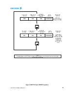
condition. The fault condition may be reset by re-setting power to the MCPA. Refer to
Figure 4 for sequence.
4.4.3 Amplitude and Phase Adjustment
The two loops are controlled via the microprocessor through the main and error driver
amplifiers. The amplifiers include vector control circuitry to adjust amplitude and phase
Содержание 1/KRB 101 1108
Страница 11: ... 2001 Ericsson Amplifier Technologies Inc ...
Страница 29: ... 2001 Ericsson Amplifier Technologies Inc ...


