© 2001 – Ericsson Amplifier Technologies Inc.
13
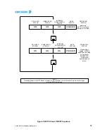
3.2.2 MCPA Power ON/OFF Sequence Summary
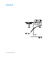
Figure 4 is a functional diagram of the MCPA Power ON/OFF sequence.
Initially, the MCPA +27 VDC and +15 VDC bias are both off.
After depressing the On/Off switch, both the ex27 VDC and +15 VDC bias are
on. Typical current without any RF applied to the MCPA is 18 amps.
Depressing the On/Off switch again will turn off the MCPA module completely, as it was
initially.
Содержание 1/KRB 101 1108
Страница 11: ... 2001 Ericsson Amplifier Technologies Inc ...
Страница 29: ... 2001 Ericsson Amplifier Technologies Inc ...


