eQ-3 Homematic HM-LC-Sw4-DR Скачать руководство пользователя страница 23

44

45

A soon as a component has been taught-in to a 

Central Control Unit, it can only be connected to 
other components via the CCU .

Each component can only be taught-in to one 
Central Control Unit .

During teach-in, please make sure you maintain 
a distance of at least 50 cm between the Home-
Matic devices and the Central Control Unit .

To teach-in your device to the Central Control Unit, 
proceed as follows:

• 

Open the „WebUI“ user interface in your browser .
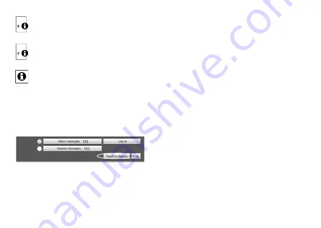
• 

Click the „Teach-in devices“ button on the right-hand 
side of the screen .

• 

To activate teach-in mode, click „BidCoS-RF teach-in 
mode“ in the next window .

• 

Teach-in mode remains activated for 60 seconds . 
An information box shows how much teach-in time 
remains . 

• 

Meanwhile, please activate the teach-in mode of the 

switching acutator to teach-in as well .

• 

Therefore, press and hold down one channel button 

for at least 4 seconds. The device LED will flash con

-

tinuously to indicate that teach-in mode is active .

• 

After a short time, the newly taught-in device will 
appear in the inbox of your software interface . The 
button „Inbox (x new devices)“ indicates how many 
new devices have been taught-in successfully .

• 

If required, you can teach-in additional devices by 
repeating the steps described above for each device . 

•  Now configure the newly taught-in devices in the 

inbox as described in the next section .

Configuring newly taught-in devices

Once you have taught-in your switching actuator to the 
HomeMatic Central Control Unit, it will be moved to 

the inbox. Here, you must configure the device and its 

associated channels in order to make them available 

for operating and configuration tasks. Give the device 

a name and assign it to a room . You can also make 
individual parameter settings . 

Now you can use the „WebUI“ user interface to control 

your device, configure it, link it directly to other de

-

vices, or use it in central control unit programs . Please 
refer to the HomeMatic WebUI manual for more details 

Содержание Homematic HM-LC-Sw4-DR

Страница 1: ...Installations und Bedienungsanleitung S 2 Installation and operating manual p 27 Funk Schaltaktor 4 fach Hutschienenmontage HomeMatic Wireless Switch Actuator 4 channel DIN rail mount HM LC Sw4 DR...

Страница 2: ...usgabe Deutsch 04 2014 Dokumentation 2014 eQ 3 AG Deutschland Alle Rechte vorbehalten Ohne schriftliche Zustimmung des Herausgebers darf dieses Handbuch auch nicht auszugsweise in irgendeiner Form rep...

Страница 3: ...ktor ist Teil einer Ge b udeinstallation Bei der Planung und Errich tung von elektrischen Anlagen sind die ein schl gigen Normen und Richtlinien des Landes zu beachten in dem die Anlage installiert wi...

Страница 4: ...chluss eines Verbrau chers unbedingt die technischen Daten insbe sondere die maximal zul ssige Schaltleistung der Relais und Art des anzuschlie enden Ver brauchers Alle Lastangaben beziehen sich auf o...

Страница 5: ...t die Funktion des Ger tes ber ein Programmierger t und Software kon figurierbar Welcher weitergehende Funktionsumfang sich damit ergibt und welche Zusatzfunktionen sich im HomeMatic System im Zusamme...

Страница 6: ...inie 1999 5 EG befindet Die vollst ndige Konformit tserkl rung finden Sie un ter www homematic com 6 Installation Beachten Sie die Installationsvorschriften f r Installationen in Verteilersystemen Der...

Страница 7: ...zeuges der Messge r te und ggf der pers nlichen Schutzausr stung Auswertung der Messergebnisse Auswahl des Elektro Installationsmaterials zur Si cherstellung der Abschaltbedingungen IP Schutzarten Ein...

Страница 8: ...se Kanal 1 3 1 3 5 Au enleiteranschluss Kanal 2 4 1 4 5 Geschaltete Phase Kanal 2 1 4 1 8 Au enleiteranschluss Kanal 3 2 4 2 8 Geschaltete Phase Kanal 3 3 4 3 8 Au enleiteranschluss Kanal 4 4 4 4 8 Ge...

Страница 9: ...c Kompo nenten z B eine HomeMatic Fernbedienung kom munizieren kann muss das Ger t zun chst angelernt werden Sie k nnen den HomeMatic Funk Schaltaktor an andere HomeMatic Ger te oder an die HomeMatic...

Страница 10: ...ie nur noch ber diese mit an deren Komponenten verkn pft werden Jede Komponente kann immer nur an eine Zen trale angelernt werden Halten Sie beim Anlernen einen Mindestabstand von 50 cm zwischen den H...

Страница 11: ...M glichkeit einzelne Parametereinstellungen vorzunehmen Anschlie end k nnen Sie Ihr Ger t ber die WebUI steuern und konfigurieren direkt mit anderen Ger ten verkn pfen oder in Zentralenprogrammen nutz...

Страница 12: ...etzspannung berpr ft der Aktor seine Komponenten Sollte dabei ein Fehler festgestellt werden so wird dieses durch gemeinsa mes Blinken aller Kanal LEDs dargestellt Dieses wie derholt sich kontinuierli...

Страница 13: ...Schaltausg nge Relais Schlie er Lastart ohmsche Last Maximale Schaltleistung 3680 W 230 V 50 Hz 16 A pro Kanal Summe aller Kan le max 25 A 5750 W Leitungsart und querschnitt starre Leitung 0 14 2 5 m...

Страница 14: ...ll be implemented in the next edition We accept no liability for technical or typographical errors or the consequences thereof All trademarks and industrial property rights are acknowledged Printed in...

Страница 15: ...47 10 1 Flashing codes 47 10 2 Operating status display 47 11 Response to power recovery 48 12 Maintenance and cleaning 48 13 Technical data 49 1 Information about this manual Read this manual careful...

Страница 16: ...y be operated indoors and must be protected from the effects of damp and dust as well as solar or other methods of heat radiation Using this device for any purpose other than that described in this op...

Страница 17: ...switches up to 4 connected consumers with total switching capacity of 5750 W 230 V 25 A or 3680 W 230 V 16 A per channel on the basis of received radio commands Commands are transmitted by actuating b...

Страница 18: ...of interference occurring Interference can also be caused by switching opera tions electrical motors or defective electrical devices The range of transmission within buildings can differ greatly from...

Страница 19: ...er the technical connection requirements TAB of your energy supplier Only to be installed by persons with the relevant electro technical knowledge and experience Incorrect installation can put your ow...

Страница 20: ...Place the switching module onto the DIN rail and lock it in position Make sure that the locating springs engage properly and that the device is securely seated on the rail Strip 8 mm from the ends of...

Страница 21: ...Permitted cable cross sections for connecting to the actuator Rigid cable mm2 Flexible cable with ferrule mm2 0 14 2 50 0 14 1 50 7 Start up 7 1 Simple operator functions using inte grated buttons The...

Страница 22: ...Activate the teach in mode of your switching actua tor Therefore press and hold down the channel but ton for at least 4 seconds The device LED will flash continuously to indicate that teach in mode is...

Страница 23: ...he device LED will flash con tinuously to indicate that teach in mode is active After a short time the newly taught in device will appear in the inbox of your software interface The button Inbox x new...

Страница 24: ...is in teach in mode hold the first channel button down for at least four seconds again If the device LED flashes quickly this indicates that the actuator is being reset 10 Device LED feedback 10 1 Fl...

Страница 25: ...o carry out any repairs Disconnect the device from the power supply system before commencing cleaning Use a dry linen cloth to clean the device If the device is particularly dirty you can slightly dam...

Страница 26: ...e of the device with regular do mestic waste Electronic equipment must be disposed of at local collection points for waste electronic equipment in compliance with the Waste Electrical and Electronic E...

Страница 27: ...52 Bevollm chtigter des Herstellers Manufacturer s authorised representative eQ 3 AG Maiburger Stra e 29 26789 Leer GERMANY www eQ 3 de...

Отзывы: