background image

Rev. 

B

 Installation   

2-5

UB-S09 Developer's Guide

Confidential

Note: 

• 

DM-D connection is selected from JP1; however if no DM-D is actually connected to the connector of the

        UB-S09, the RTS signal will always be BUSY.

      • 

Operations are based on these JP1 or TM printer settings even if the DM-D is not actually connected.

WARNING:

Never connect display connectors to both the UB-S09 and TM printer at the same time.

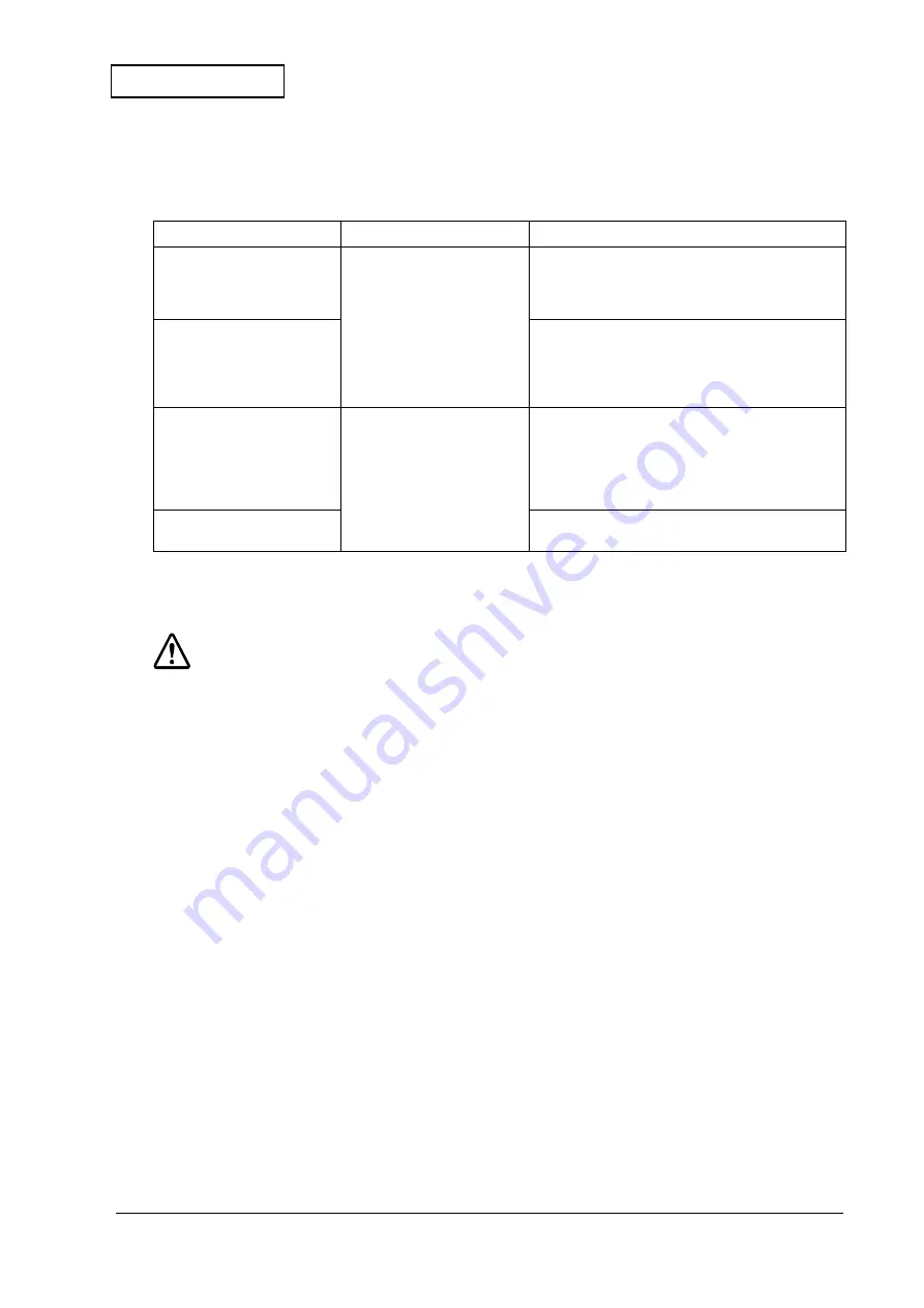
Table 2-4  Customer display connection settings and operations 2

UB-S09 DM-D connector

TM printer connector

Operations

DM-D not connected
(JP1: 2-3 shorted)

DM-D not connected
DIP switch OFF


ESC= 

default of TM printer: Printer select

• 

Self test print: Will not be recognized

• 

GS I

: Sends DIP switch off status

• 

RTS signal: No DM-D status output

DM-D connected
(JP1: 1-2 shorted)

 ESC=

 default of TM printer: Printer select

• 

Self test print: Will not be recognized

• 

GS I

: Sends DIP switch OFF status

• 

RTS signal: DM-D status output from UB-S09

  connector.

DM-D not connected
(JP1: 2-3 shorted)

DM-D connected
DIP switch ON

 ESC= 

default of TM printer: DM-D select

• 

Self test print: Must be connected

• 

GS I

: Sends DIP status output from TM printer

   connector

• 

RTS signal: DM-D status output from TM printer 

   connector

DM-D connected
(JP1: 1-2 shorted)

This setting is prohibited

Содержание UB-S09

Страница 1: ...Confidential Developer s guide Serial interface board UB S09 English 401357701 Issued date Issued by EPSON ...

Страница 2: ...SEIKO EPSON CORPORATION Printed in Japan EPSON ...

Страница 3: ... information on the document You may not reproduce store or transmit the confidential information in any form or by any means electronic mechanical photocopying recording or otherwise without the prior written permission of Seiko Epson Your obligations under this Agreement are in addition to any other legal obligations Seiko Epson does not waive any right under this Agreement by failing to exercis...

Страница 4: ...tations 1 3 Chapter 2 Installation Installation Precautions 2 1 Package Contents 2 2 Jumper Settings 2 2 Jumper JP1 Settings 2 2 Jumper JP2 Settings 2 2 Jumper Locations 2 3 Customer Display Connection Setting 2 4 TM Printer with No DM D Connector 2 4 TM Printer with a DM D Connector 2 4 Circuit Board Installation 2 6 Cable Connection 2 7 Interface Cable Connection 2 7 Customer Display Cable Conne...

Страница 5: ... important for maintaining the product and useful information for handling the product Labels on the Product A warning label like the following is attached near the modular connector on this product The label should be understood to have the following meaning WARNING This product uses a modular connector for the customer display Never connect a telephone line to this connector Purpose of this Docu...

Страница 6: ... bits per second Handshaking communications speed data bit length and parity are set by DIP switches on the TM Printer Table 0 1 Related Documents Document Contents UB S09 Specifications Detailed specifications of the UB S09 UB S09 Operating Manual Intended for POS terminal operators this manual provides information on handling the UB S09 safely and correctly Supported standard EIA TIA RS 232 stan...

Страница 7: ...ial The parts of the UB S09 are named as follows Revision Information Revision Page Altered Items and Contents Rev A Rev B 2 2 2 6 Description of hex mounting screws eliminated Customer Display Connector Serial Interface Connector Warning Label ...

Страница 8: ...vi Rev B Confidential ...

Страница 9: ...le 1 2 shows the relationship between jumper JP2 on the UB S09 and DIP switch DSW2 7 on the TM printer 2 To reset the TM printer through the interface the reset signal can be applied to pin 6 or pin 9 Table 1 1 Recommended wiring Host side UB S09 side Female 9 pin D sub Pin 1 not connected TXD Pin 2 RXD RXD Pin 3 TXD DSR Pin 4 DTR SG Pin 5 SG DTR Pin 6 DSR 1 2 CTS Pin 7 RTS RTS Pin 8 CTS Reserved ...

Страница 10: ...used with the UB S09 Transmission Speed When using the UB S09 the transmission speed must be set at the same transmission speed for both the TM printers and the UB S09 Confirm both transmission speeds and set the DIP switches for the transmission speed properly Dimensions The external dimensions of the UB S09 are shown below Figure 1 1 UB S09 External dimensions Table 1 3 Incompatible combination ...

Страница 11: ...temperature and humidity specifications Other Limitations The power supply for the customer display is not switched on and off by the TM printer power switch As long as power is supplied to the TM printer except the TM J8000 power connector power is continuously supplied to the customer display The customer display can only be turned off by the power switch on the display ...

Страница 12: ...1 4 System Preparation Rev B Confidential ...

Страница 13: ...tive objects such as paper clips on the circuit board as they could short circuit connections and cause damage from excessive current This product should only be connected with the devices specified in this document Connecting other devices could cause damage fire or explosion Do not attempt to wire this product other than as described in this document Improper wiring could cause damage fire or ex...

Страница 14: ...t in Chapter 3 for a description of the functions of pin 6 DSR of the serial connector The jumper settings are described below Jumper JP1 Settings As shipped from the factory pins 2 and 3 of JP1 are shorted Note Do not set JP1 open without jumper If you short pins other than 1 and 2 or 2 and 3 of JP1 the UB S09 will not operate correctly Table 2 1 Customer display connection settings JP 1 1 2 shor...

Страница 15: ...jumper Shorting pins other than 1 and 2 or 2 and 3 of JP2 could cause incorrect operation or damage to the UB S09 communications IC Jumper Locations The jumper locations are shown below Figure 2 1 Jumper Locations Table 2 2 Serial Connector Pin 6 DSR Function Settings JP2 1 2 shorted 2 3 shorted Settings Select reset up on Mark input Select reset up on Space input 3 2 1 3 2 1 ...

Страница 16: ...ctually connected TM printer with a DM D Connector The customer display cable can be connected to either the connector on the UB S09 or on the TM printer however it is recommended to connect the cable to the connector on the TM printer The TM printer must be set to enable the DM D connection by the DIP switch on the TM printer For details refer to the DIP switch section in the specification of eac...

Страница 17: ...ns DM D not connected JP1 2 3 shorted DM D not connected DIP switch OFF ESC default of TM printer Printer select Self test print Will not be recognized GS I Sends DIP switch off status RTS signal No DM D status output DM D connected JP1 1 2 shorted ESC default of TM printer Printer select Self test print Will not be recognized GS I Sends DIP switch OFF status RTS signal DM D status output from UB ...

Страница 18: ... Board Installation 1 If an interface circuit board is already installed in the TM printer remove it Re use the screws when installing the UB S09 2 Install the UB S09 in the TM printer and tighten the screws Install the UB S09 using these screws ...

Страница 19: ...onnected to the printer at either of the two UB S09 mounting screws 4 Connect the other end of the cable to the host computer Customer Display Cable Connection 1 Confirm that the printer and host computer are turned off 2 Disconnect the Power Unit from the printer WARNING The Power Unit MUST be disconnected from the printer Even when the printer is turned off power is supplied to the customer disp...

Страница 20: ...2 8 Installation Rev B Confidential WARNING Never connect a public telephone line to this connector 4 Reconnect the Power Unit to the printer Customer Display Cable Connector ...

Страница 21: ...ce Turn power off using the following sequence 1 Turn the customer display off 2 Turn the TM printer off The power supplied to the customer display is not switched on and off by the TM printer power switch As long as power is supplied to the TM printer excluding TM J8000 printer power connector power is continuously supplied to the customer display Use the power switch on the customer display to t...

Страница 22: ...3 2 Operation Rev B Confidential ...

Страница 23: ...tus indicates that the host is ready to receive and the Mark status indicates that the host is not able to receive The RTS signal indicates the BUSY READY status of the TM printer and the customer display When either one is BUSY the RTS signal will be RTS BUSY Confirm the RTS signal when sending data for the customer display Table 4 1 TM printer BUSY conditions Printer DIP Switch Setting Printer B...

Страница 24: ...m online refers to the state when any of the above conditions has been cancelled The UB S09 does not provide a data line connection from the customer display to the host so XON XOFF handshaking cannot be selected for the customer display Select DTR RTS when connecting the customer display Table 4 2 TM printer XON XOFF sending conditions Printer DIP Switch Setting XON XOFF Sending Sending Condition...

Страница 25: ... resetting using pin 6 DSR To use pin 9 INIT the reset signal logic is fixed at Space level To reset the printer the reset signal must conform to the electrical characteristics specified in the UB S09 Specifications Table 4 3 Reset Signal Logic Selection Jumper JP2 Setting Reset Condition Reset by pin 6 DSR 1 2 shorted Reset upon Mark level reset occurs when this pin is open circuit 2 3 shorted Re...

Страница 26: ...4 4 Function Description Rev B Confidential ...

Страница 27: ... consists of the DTR signal logic of the customer display and the printer When the Customer Display DM D Connection switch is set to Not Connected the output is the same as the DTR signal Table A 1 RS 232 serial interface connector pinout Pin Signal name I O Signal function 1 No connection 2 RxD I Receive Data 3 TxD O Transmit Data 4 DTR O DTR signal 5 SG Signal Ground 6 DSR I DSR signal 7 RTS O S...

Страница 28: ...Appendix A 2 Connector Terminal Signals Rev B Confidential ...

Отзывы: