TM200 Service Manual
- 22 -
CPU peripheral logic circuits
RAM (128K byte)
RAM is used for temporary storage of the following:
Data received from the interface (receive buffer)
Pattern data printed by the print head unit (printer buffer)
Data used for CPU routines (flags, pointers, etc.)
Flash memory (2M or 8M bits)
A printer control program and character generator data is written into flash memory.
The control program controls basic printer operations, and all CPU control is
performed in accordance with this program. Another flash memory works as a
sub-memory for such items as expanding character generator data.
RS-232C interface specifications
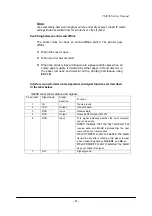
Selection between two signals (pin 6 (DSR) or pin 25 (INIT)) is possible.
TM200 Control Circuit
Thermal head driver circuit
The print head of the receipt printer mechanism is a thermal type print head with 576
dots per line. All print head control is performed via a gate array. A driver is built into
the print head, and sending of print signal DATA-IN, which is synchronized with the
CLOCK signal, to the driver sets the print/non-print status of each dot. Data is
confirmed by latch signal #LATCH. Print time control is performed by #STROBE1 and
#STROBE2, while energizing time is controlled by the gate array.
Changes in head temperature causes fluctuation of the resistance value of the
thermistor built into the head, which is output as temperature signal THERMISTOR.
Paper feed motor driver circuit
The paper feed motor is constant-current driven by a special-purpose IC. The
energizing direction switching signals (PH1,PH2,PH3 and PH4) from the CPU. The
special-purpose IC controls the paper feed motor in accordance with these signals
using Q1, Q2, Q3, and Q4 signals.
Autocutter driver circuit
The autocutter driver use MOSFET to control DC motor.
Detector circuits
Paper end sensor circuit
The thermal printer mechanism is equipped with a paper end sensor, which is
connected via switch circuit board assembly to the main circuit board unit. The paper
end signal FP_Sensor is input to the DSP’s port.
Cover open sensor circuit

