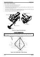
3.2.4 Printer Mechanism (M-4A10) Removal
1.
Remove the upper case (see Section 3.2.1).
2.
Remove the power supply unit (see Section 3.2.2).
3.
Remove the main controller (see Section 3.2.3).
4.
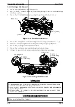
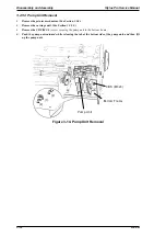
Remove the 4 CBN (M4
×
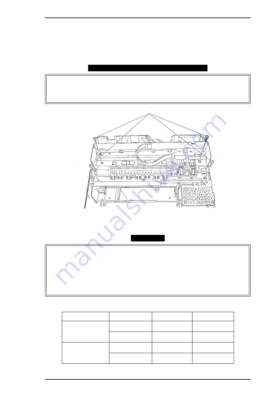
13) screws and take out the printer mechanism.
DISASSEMBLY/ASSEMBLY POINT
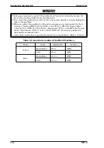
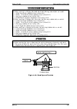
Wipe off any ink around the end of the ink drain tube when you remove the printer
mechanism.
❏
When reinstalling the printer mechanism, check that the waste ink drain tube is properly
inserted between the lower case and the waste ink absorbing material.
CAUTION
When you replace the printhead or printer mechanism, you must replace the block
resistor at location RM4 (for Micro Mode - Color (R-No.)), RM5 (for Normal Mode -
Color (M-No.)), RM11 (for Micro Mode - Monochrome (R-No.)), and RM12 (for Normal
Mode - Monochrome (M-No.)) on the C162 MAIN Board. (Every spare printhead or
spare printer mechanism comes with a block resistor that is specifically selected for
each printhead.) Refer to Table 3-1.
❏
Adjust both the head gap and bidirectional alignment when replacing the printer
mechanism.
Table 3-1. Insertion Location for Block Resistors
Mode
Head
Indication No.
Location
Normal
Monochrome
M-
××
RM12
^
Color
M-
××
RM5
Micro
Monochrome
R-
×× ×
RM11
^
Color
R-
×× ×
RM4
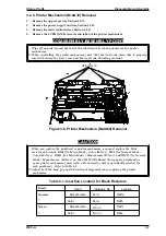
CBB (M4x13 )
Figure 3-6. Printer Mechanism (M-4A60) Removal
Stylus Pro XL
Disassembly and Assmbly
REV.-A
3-7
Содержание Stylus Pro XL
Страница 1: ...EPSON COLOR INKJET PRINTER Stylus Pro XL SERVICE MANUAL EPSON 4004677 ...
Страница 93: ...Rev A 5 i ...
Страница 127: ...EPSON ...

