8. APPLIED CIRCUIT EXAMPLES
S1F76640 Technical Manual (Rev.1.5)
EPSON
23
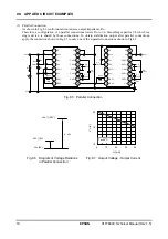
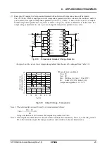
(7) Example of Changing the Temperature Gradient with an External Temperature Sensor (Thermistor)
The S1F76640, which is equipped with the temperature gradient selection circuit in the stabilizer, enables
you to select three types of temperature gradients (-0.30%/
°
C, -0.40%/
°
C, and -0.50%/
°
C) as V
REG
output.
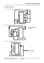
If other temperature gradients are required, as shown in Fig.8.18, connect a thermistor to resistor R
RV
(for
output voltage adjustment) in series; you can change the temperature gradient to any value.
Fig.8.18 Temperature Gradient Change Example
(For pins 3 and 4, select a lower temperature gradient than the one to be changed from Table 5.1.)
1
2
3
4
5
6
7
8
9
10
11
12
13
14
15
16
OSC2
OSC1
V
SS
XP
OFF
TC2
TC1
V
REG
RV VRI
V
OUT
CAP1
+
CAP1
−
CAP2
−
CAP2
+
CAP3
+
V
DD
C4
10
μ
F
V
OUT
R
OSC
1M
Ω
C1
10
μ
F
+
−
C2
10
μ
F
C3
10
μ
F
V
DD
V
REG
V
SS
R
T
R
P
Note 2
R2
R1
R
RV
1M
Ω
+
−
+
−
+
−
-10
-8
-6
-4
-2
0
2
4
6
8
10
0
10
20
30
40
50
Ta [°C]
100×|V
REG
(°
C)|-|V
REG
(25°
C)|/
|V
REG
(25°
C)| [
%
]
Thermistor used
Thermistor not used
[Measurement conditions]
V
DD
: 5V
V
SS
: 0V
R
RV
: 1M
Ω
(set to V
REG
= 10 at 25
°
C)
R
T
: 10k
Ω
(0
°
C/50
°
C Ratio 9.00)
Temperature gradient: -0.3 %/
°
C
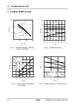
Fig.8.19 Output Voltage - Temperature
Note 1: The relationship between R
T
and V
REG
is indicated as follows:
Using a thermistor as R
T
increases the temperature gradient for V
REG
.
R
PV
+
R
T
V
REG
= R
V
R1
Note 2: The temperature characteristics of the thermistor indicate the nonlinearity; however, connecting resistor
R
P
to the thermistor in parallel changes nonlinear characteristics to linear characteristics.

