08. APPLIED CIRCUIT EXAMPLES
18
EPSON
S1F76640 Technical Manual (Rev.1.5)
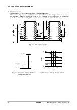
(3) Parallel
Connection
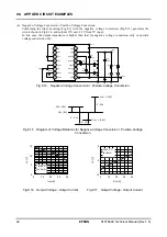
As shown in Fig.8.1, multi-connection reduces output impedance Ro.
Therefore, a configuration of n parallel connections lowers Ro to 1/n. Smoothing capacitor C4, which is a
single device, is shared by those connections. To obtain stabilization output after parallel connections,
apply the connection shown in Fig.8.3 to only one of the n parallel connections shown in Fig.8.5.
1
2
3
4
5
6
7
8
9
10
11
12
13
14
15
16
OSC2
OSC1
V
SS
XP
OFF
TC2
TC1
V
REG
RV VRI
V
O
CAP1
+
CAP1
−
CAP2
−
CAP2
+
CAP3
+
V
DD
C4
10
μ
F
R
OSC
1M
Ω
C1
10
μ
F
+
−
C2
10
μ
F
C3
10
μ
F
V
DD
R2
R1
V
REG
R
RV
1M
Ω
1
2
3
4
5
6
7
8
9
10
11
12
13
14
15
16
OSC2
OSC1
V
SS
XP
OFF
TC2
TC1
V
REG
RV
VRI
V
O
CAP1
+
CAP1
−
CAP2
−
CAP2
+
CAP3
+
V
DD
R
OSC
1M
Ω
C1’
10
μ
F
C2’
10
μ
F
C3’
10
μ
F
V
SS
A
V
OUT
R
L
I
O
+
−
+
−
+
−
+
−
+
−
+
−
Fig.8.5 Parallel Connection
10
15
20
0
10
20
30
40
I
O
[mA]
V
O
[V]
Ta=25°C
V
SS
(0V)
V
DD
(
+
5V)
V
OUT
(
+
20V)
4
$
V
DD
Fig.8.6 Diagram of Voltage Relations Fig.8.7 Output Voltage - Output Current
in Parallel Connection

