


13. Overview of Functions and Registers
RX4111CE
Jump to
ETM62E-02
Seiko Epson Corporation
23
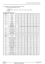
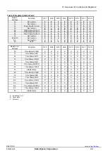
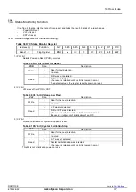
13.3. Description Of Registers
13.3.1. Clock and Calendar Counter
(Bank1 - 1h ~ 6h)
This is counter registers from a second to a year.
Please refer to [14.1
Clock calendar explanation] for details.
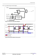
13.3.2. Timer Setting and Timer Counter Register
(Bank1 - Ah ~ Ch)
This register is used to set the default (preset) value for the counter.
To use the Wake-up timer interrupt function, TE,
TF,
TIE,
TSEL1,
TSEL0, TBKON, TBKE, TSTP, TMPIN bits are
set and used.
When the Wake-up timer interrupt function is not being used, the Wake-up timer control register
can be used as a RAM register. In such cases, stop the Wakeup timer function by writing 0 to the TE and TIE bits.
Please refer to [14.2. Wakeup Timer Interrupt Function] for the details.
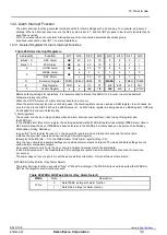
13.3.3. Alarm Registers
(Bank1
– 7h ~ 9h, Bank2 - Ch)
The alarm interrupt function is used, along with the AE, AF, and WADA bits, to set alarms for specified date, day, hour,
minute, and second values.
Please refer to [14.3. Alarm Interrupt Function] for the details.
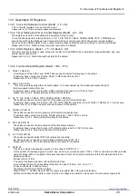
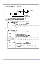
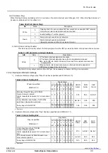
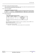
13.3.4. Function-Related Register (Bank1 - 1Dh ~ 1Fh)
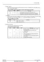
1) FSEL1, FSEL0 bit
A combination of the FSEL1 and
FSEL0 bits are used to select the frequency to be output.
If customer does not use this function, FESL1, FSEL0 should be set to 1.
Please refer to 14.6 FOUT Function
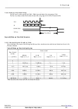
2) USEL, UF, UIE bit
This bit is used to specify either
“second update” or “minute update” as the update generation timing of
the time update interrupt function.
If customer does not use this function, USEL, UIE should be reset to 0
. UF do not care.”.
Please refer to [14.4. Update interrupt function] for the details.
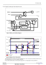
3) TE, TF, TIE, TSEL1, TSEL0, TSTP, TBKON, TBKE, TMPIN bit
These bits are used to control operation of the wake-up timer interrupt function.
If customer does not use this function, (TE, TIE, TSTP, TMPIN) should be (0,0,0,0), TSEL1, TSEL0(1,0). TF do not care.
Please refer to [14.2 Wake-up timer interrupt function] for the details.
4) WADA, AF, AIE bit
These bits are used to control operation of the alarm interrupt function.
If customer does not use this function, WADA should be 1, AIE 0. AF do not care.
Please refer to [14.3. Alarm interrupt function] for the details.
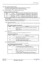
5) ETS, EVF, EIE bit
These bits are used to control operation of the time stamp function.
If customer does not use this function, ETS, EIE should be reset to 0. EVF do not care.
Please refer to [14.8. Time Stamp function] for the details.
6) VLF, POR, XST bit
These bits are used to detect RTC inner status and recording.
Ex. During power on resetting, lower voltage detection makes VLF bit 1.
Please refer to [14.5. RTC inner status detection function] for the details.
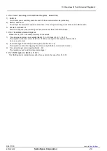
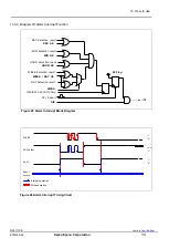
7) STOP bit
This bit is to stop a timekeeping operation. In the case of “STOP bit = 1”:
All the update of timekeeping (year, month, day, week, hour, minute, second, 1/128 s, 1/512 s) operation and the calendar
operation stops. With it, an update interrupt event does not occur at an alarm interrupt and the time stamp data is to be
stopping condition.
(Please refer to 14.8.5)
The part of the fixed-cycle timer interrupt function stops.
A count stops the source clock setting of the timer in case of
“64 Hz, 1 Hz, 1 min, 1 h”.
(In case of 4096 Hz, it does not stop.)
The effect of STOP bit to FOUT functions.
When STOP = 1, 32.768 kHz and 1024 Hz output is possible. But 1 Hz output is disabled.
Switchover function cannot work in order that the V
DD
voltage drop detection stops even if a main power supply falls.


