Disassembly and Assembly
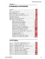
Chapter 4
Disassembly and Assembly
Precautions .............................................................................................
Tools ........................................................................................................
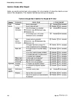
Service Checks After Repair ...................................................................
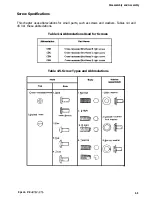
Screw Specifications ...............................................................................
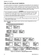
Notes for Unit Removal and Installation ............................................... 4-4
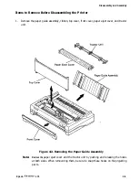
Items to Remove Before Disassembling the Printer ............................. 4-5
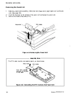
Removing the Panel Unit .......................................................................
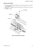
Removing the Printhead ........................................................................
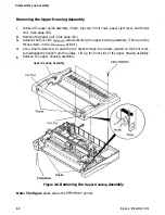
Removing the Upper Housing Assembly ............................................... 4-8
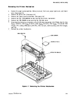
Removing the Printer Mechanism ......................................................... 4-9
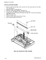
Removing the Platen Assembly ................................................ 4-10
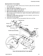
Removing the Rear Frame Assembly ....................................... 4-11
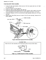
Removing the CR Motor Assembly ........................................... 4-12
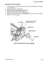
Removing the PF Motor Assembly ........................................... 4-13
Disassembling the PF Gear Train ............................................ 4-14
Removing the Carriage Guide Assembly ................................. 4-15
Removing the Ribbon Drive (RD) Assembly ............................ 4-17
Removing the Home Position (HP) Sensor ............................... 4-18
Removing the Platen Gap (PG) Sensor .................................... 4-18
Removing the Front and Rear Paper End (PE) Sensors...... ....... .4-19
Removing the Release Sensor ................................................... 4-20
Arranging the Cables ................................................................
Disassembling the Tractor Unit ............................................... 4-22
Removing the C094 MAIN Board Assembly ............................ 4-23
Removing the C076 PSB Board Assembly ............................... 4-24
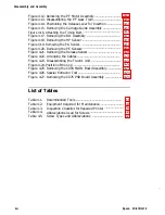
List of Figures
Figure 4-1. Flowchart for Disassembling the Printer ......................... 4-4
Figure 4-2. Removing the Paper Guide Assembly .............................. 4-5
Figure 4-3. Removing the Panel Unit .................................................. 4-6
Figure 4-4. Connecting the FFC Cable to the Panel Unit .................. 4-6
Figure 4-5. Removing the Printhead ................................................... 4-7
Figure 4-6. Removing the Upper Housing Assembly .......................... 4-8
Figure 4-7. Removing the Printer Mechanism .................................... 4-9
Figure 4-8. Removing the Platen Assembly ...................................... 4-10
Figure 4-9. Removing the Rear Frame Assembly ............................. 4-11
Figure 4-10. Removing the CR Motor Assembly ................................. 4-12
Figure 4-11. Positioning the CR Motor Assembly ............................... 4-12
Epson FX-870/1170
4-i
Содержание FX-1170
Страница 1: ...FX 870 1170 SERVICE MANUAL I Revision Level I EPSON Printed on Recycled Paper ...
Страница 112: ......
Страница 159: ...Reference Materials I Figure 73 C094 MAIN Board Assembly Circuit Diagram 7 6 Epson FX 87CY1170 ...
Страница 164: ...Reference Materials n EEm EPS I I MODEL 1 Figure 7 8 CO76 PSB Board Assembly Component Layout Epson FX 870 1170 7 11 ...
Страница 166: ...Reference Mater Outline Drawings I r I 380 I I I I i I Figure 7 10 FX 870 Case Outline Drawing Epson FX 870 1170 7 13 ...
Страница 167: ...Reference Materials I L I r r I I r 01 z Figure 7 11 F X 1170 Case Outline Drawing 7 14 Epson FX 870 1170 ...

