Troubleshooting
Chapter 3
Troubleshooting
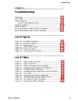
Test Points ................................................................................................
Error Codes ...............................................................................................
Problem Isolation .....................................................................................
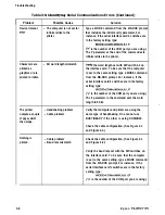
Serial Communications Errors ........................................................ 3-7
Connector Locations ...............................................................................
Sensor Locations .....................................................................................
Hex Quick Reference Table for ESC/P Commands ............................... 3-21
Hex Quick Reference Table for IBM Commands ................................... 3-23
List of Figures
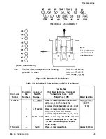
Figure 3-1. Printhead Resistance .......................................................... 3-3
Figure 3-2. Connector Locations ..........................................................
Figure 3-3. Release Sensor ...................................................................
Figure 3-4. Home Position Sensor ....................................................... 3-19
Figure 3-5. Platen Gap Sensor .............................................................
Figure 3-6. Front and Rear PE Sensors .............................................. 3-20
List of Tables
Table 3-1.
Power Supply Test Points ................................................... 3-1
Table 3-2.
Sensor Test Points ...............................................................
Table 3-3.
Motor Test Points and Coil Resistance ............................... 3-2
Table 3-4.
Printhead Test Points and Coil Resistance ....................... .3-3
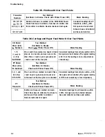
Table 3-5.
Printhead Driver Test Points .............................................. 3-4
Table 3-6.
Carriage and Paper Feed Motor Driver Test Points ......... .3-4
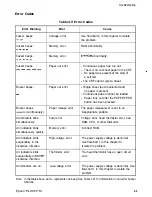
Table 3-7.
Error Codes ..........................................................................
Table 3-8.
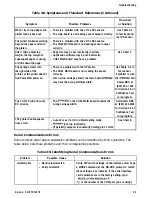
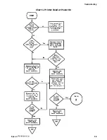
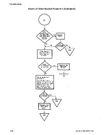
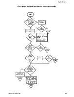
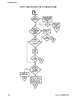
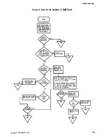
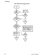
Symptoms and Flowchart References ................................. 3-6
Table 3-9.
Identifying Serial Communications Errors ....................... 3-7
Table 3-10. Hex Codes for ESC/P Commands ..................................... 3-21
Table 3-11. Hex Codes for IBM Commands ......................................... 3-23
Epson FX-870/1170
3-i
Содержание FX-1170
Страница 1: ...FX 870 1170 SERVICE MANUAL I Revision Level I EPSON Printed on Recycled Paper ...
Страница 112: ......
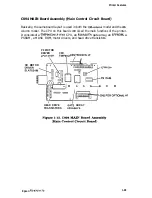
Страница 159: ...Reference Materials I Figure 73 C094 MAIN Board Assembly Circuit Diagram 7 6 Epson FX 87CY1170 ...
Страница 164: ...Reference Materials n EEm EPS I I MODEL 1 Figure 7 8 CO76 PSB Board Assembly Component Layout Epson FX 870 1170 7 11 ...
Страница 166: ...Reference Mater Outline Drawings I r I 380 I I I I i I Figure 7 10 FX 870 Case Outline Drawing Epson FX 870 1170 7 13 ...
Страница 167: ...Reference Materials I L I r r I I r 01 z Figure 7 11 F X 1170 Case Outline Drawing 7 14 Epson FX 870 1170 ...


