and Assembly
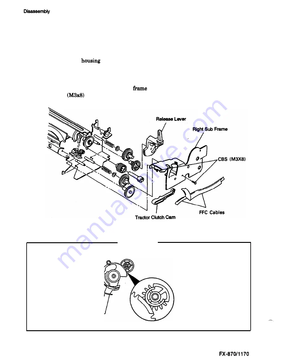
Disassembling the PF Gear Train
1.
Remove
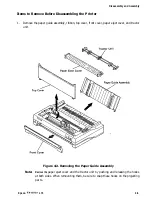
the paper guide assembly, top cover, front cover, paper eject cover, and tractor unit.
(See page 4-5.)
2.
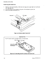
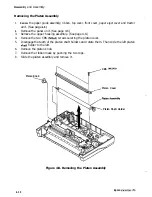
Remove the panel unit. (See page 4-6.)
3.
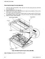
Remove the upper
assembly. (See page 48.)
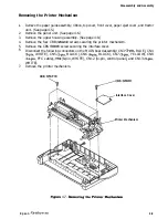
4.
Remove the printer mechanism. (See page 4-Q.)
5.
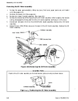
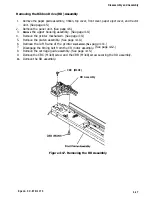
Remove the CR motor assembly. (See page 4-12.)
6.
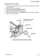
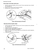
Remove the PF motor assembly. (See page 4-13.)
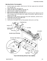
7.
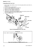
Remove the FFC cables
from
the right sub
of the printer mechanism, and then remove
the two CBS
screws securing the right sub frame.
8.
Remove the right sub frame.
Figure 4-13. Disassembling the PF Gear Train
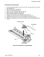
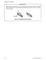
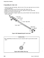
Assembly Note
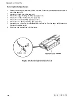
Be sure
to mesh the release lever with the mechanism properly.
Figure 4-14. Positioning the Release Lever for
Insertion
4-14
E p s o n
Содержание FX-1170
Страница 1: ...FX 870 1170 SERVICE MANUAL I Revision Level I EPSON Printed on Recycled Paper ...
Страница 112: ......
Страница 159: ...Reference Materials I Figure 73 C094 MAIN Board Assembly Circuit Diagram 7 6 Epson FX 87CY1170 ...
Страница 164: ...Reference Materials n EEm EPS I I MODEL 1 Figure 7 8 CO76 PSB Board Assembly Component Layout Epson FX 870 1170 7 11 ...
Страница 166: ...Reference Mater Outline Drawings I r I 380 I I I I i I Figure 7 10 FX 870 Case Outline Drawing Epson FX 870 1170 7 13 ...
Страница 167: ...Reference Materials I L I r r I I r 01 z Figure 7 11 F X 1170 Case Outline Drawing 7 14 Epson FX 870 1170 ...

