background image

Epson DFX-9000 Field Repair Guide

3/29/07

Printer Component, 

Software Item, 

LCD Display, 

Printer Button

 Page 201.

5.

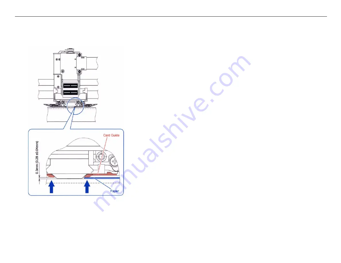
Place 3 sheets of 20 lb. paper into the gap between the 

Card Guide

 and the 

Platen

 as shown below and lightly 

push the 

Card Guide

 against the paper.

6.

Tighten the 2 screws securing the 

Card Guide

.

Содержание DFX-9000

Страница 1: ...EPSONDFX 9000 Serial Impact Dot Matrix Printer FIELD REPAIR GUIDE ...

Страница 2: ... being informed of them The contents of this manual are subject to change without notice The above not withstanding SEIKO EPSON CORPORATION can assume no responsibility for any errors in this manual or the consequences thereof EPSON is a registered trademark of SEIKO EPSON CORPORATION General Notice Other product names used herein are for identification purpose only and may be trademarks or regist...

Страница 3: ... or maintenance procedure practice or condition that if not strictly observed could result in damage to or destruction of equipment May indicate an operating or maintenance procedure practice or condition that is necessary to accomplish a task efficiently It may also provide additional information that is related to a specific subject or comment on the results achieved through a previous action In...

Страница 4: ...This page was left blank intentionally ...

Страница 5: ...acement 7 Front Cover Assembly 8 Rear Cover 10 Control Panel 12 Upper Case 14 Mechanism Removal 16 Print Head Removal 20 Ribbon Mask Ribbon Mask Holder Removal 21 Ribbon Mask Removal 24 Carriage Motor SP Motor 25 Ribbon Drive Assembly Removal 31 APTC Unit Automatic Platen Gap Assembly 34 Carrier Unit Carriage Assembly Removal 36 LF Motor Paperfeed Motor Removal 39 Main Logic Board Removal 41 Front...

Страница 6: ...ltage Error 122 O7 Low Voltage Error 122 O8 Over Load Error 122 O9 Fan1 Driver Error 123 OA Fan2 Driver Error 123 OB Fan3 Driver Error 124 OC Fan4 Driver Error 124 OD No Head Error 125 OE Head Driver Error 125 OF APTC Error 126 11 Ribbon Feed Driver Error 127 12 Ribbon Jam Error 127 13 HCPP Host computer Controlled Paper Path Driver Error 128 14 HCPP Host computer Controlled Paper Path Error 129 1...

Страница 7: ...ts missing or extra dots printed 135 Incorrect horizontal character spacing 135 Smudges on paper 136 Light Print Characters have uneven upper or lower edges 136 Missing portions of the print 137 Ribbon Jam Error 138 No Paper Feed from either paper path 138 Intermittent Paper Feed from either paper path 138 Paper path does not switch properly 139 Paper Load Position TOF is incorrect 139 No paper un...

Страница 8: ...PTC Motor 158 Motor Test Points 151 Sensors and Switches 159 Sensors and Switches Test Points 145 Adjustments 162 APTC Unit Mount Position Adjustment 162 Card Guide Mount Position Adjustment 164 Parallelism Adjustment 168 APTC Thickness Detection Adjustment 179 APTC Detection Position Adjustment 192 APTC Unit Mount Position Adjustment 198 Card Guide Mount Position Adjustment 199 Parallelism Adjust...

Страница 9: ... v Revision History Date Revision Details December 1 2005 Initial Release September 1 2006 Added Motors Sensors and Switches Test Points October 3 2006 Corrected errors in Component Replacement Chapter Added Adjustments Chapter March 29 2007 Added Front and Rear Tractor Removal and Installation procedures ...

Страница 10: ...Epson DFX 9000 Field Repair Guide 3 29 07 Control Panel Map Printer Component Software Item LCD Display Printer Button Page 1 Control Panel Map ...

Страница 11: ...anel Map Paper Path Indication Status LCD Paper Micro Feed Down Paper Micro Feed Up Paper out indicator Paper path Select Font Select Pitch Select Tear off Position Select Top Of Form Position Select Paper load Line feed and Form Feed Print Pause Hold Font Pitch to Clear print buffer Hold Tear Off Top of Form To Enter Select Type Mode ...

Страница 12: ...ause Bi Direction Adjustment LF FF Load Draft Self Test Top Of Form NLQ Self Test Pitch Selects Pitch Font Default Setting Mode LF FF Load Top of Form Data Dump LF FF Load Tear off Clears Driving Line Count for Ribbon Change Timing Pitch Font Panel Lock Out Mode Pause LF FF Load Micro Feed Down Clears EEPROM Font Pitch Front Rear Error Analysis Mode Button ...

Страница 13: ...4 Pge length front in inches 3 3 5 4 5 5 6 7 8 8 5 11 70 6 12 14 17 5 Skip perforation Off On 6 Line spacing 1 6 inches 1 8 inches 7 Left margin 0 to 80 columns 8 Right margin 1 to 136 columns 9 Platen gap Auto 0 to 14 10 Auto tear off Off On 11 Auto line feed Off On 12 Print direction Bi D Uni D 13 Software ESC P IBM PPDS Others 14 0 slash Off On 15 I F mode Auto Parallel Serial USB Optional 16 I...

Страница 14: ...ting to changed has been located use the Tear off Top of form buttons to change the setting Powering off the unit will save the settings Default Settings Menu Options 1 Label base pos Paper left edge First dot 2 Label top pos 0 216 inches to 4752 216 inches 3 Label length 0 216 inches to 4752 216 inches 4 Label left pos 0 120 inches to 1440 120 inches 5 Label width 0 120 inches to1440 120 inches 6...

Страница 15: ...Epson DFX 9000 Field Repair Guide 3 29 07 Component Replacement Printer Component Software Item LCD Display Printer Button Page 6 Component Replacement ...

Страница 16: ...m LCD Display Printer Button Page 7 Component Replacement All directional references left right top bottom front and back rear are referenced with the printer positioned as shown above Before removing any component from the DFX 9000 ensure that the AC Power source has been removed C A U T I O N ...

Страница 17: ...inter Component Software Item LCD Display Printer Button Page 8 Front Cover Assembly 1 Open the Front Cover 2 Remove the Stopper from the left side of the Front Cover Gently apply inward pressure to the clips and pull outwards to free the Stopper from the Front Cover ...

Страница 18: ...pair Guide 3 29 07 Component Replacement Printer Component Software Item LCD Display Printer Button Page 9 3 Hold the Front Cover open and apply pressure to the right 4 Pull the Front Cover forward to free it from Upper Case ...

Страница 19: ...nent Replacement Printer Component Software Item LCD Display Printer Button Page 10 Rear Cover 1 Open the Rear Cover 2 On the Rear Cover remove the 2 screws on the left side and the 2 screws on the right side that secure the Rear Cover to the hinges ...

Страница 20: ...e Rear Cover away from the printer as indicated by the blue arrow Slowly release the Hinge as indicated by red arrow Releasing the Hinge too quickly can cause personal injury or damage to the printer The hinges are spring loaded Release the hinges slowly Releasing a hinge too quickly can cause personal injury or damage to the printer C A U T I O N ...

Страница 21: ...ide 3 29 07 Component Replacement Printer Component Software Item LCD Display Printer Button Page 12 Control Panel 1 Open the Top Cover 2 Release the three tabs indicated by the arrows below that hold the Control Panel in place Tabs ...

Страница 22: ...Guide 3 29 07 Component Replacement Printer Component Software Item LCD Display Printer Button Page 13 3 Pull the Control Panel forward and disconnect the Control Panel Wiring Harness from the Control Panel Control Panel Connector ...

Страница 23: ... Button Page 14 Upper Case 1 At the back of the printer remove the two screws located at the lower left and lower right corners that secure the Upper Case 2 Grasping the lower front right and lower front left hand corners pull forward and then upward to release the hooks that fasten the Upper Case to the Lower Case ...

Страница 24: ...Epson DFX 9000 Field Repair Guide 3 29 07 Component Replacement Printer Component Software Item LCD Display Printer Button Page 15 3 Pull the Upper Case upward to completely remove the Upper Case ...

Страница 25: ... performing the steps below Steps 2 4 refer to Rear Grabs Tilt Bar and Grommet Refer to the figure below for the location of these items When performing Step 4 ensure that the Tilt Bar is positioned as indicated in the figure below to prevent damage to the wiring harness located near the Grommet Front and Rear Grabs Place bottom of Tilt Bar here Place Place bottom of Tilt Bar in the small square a...

Страница 26: ... Printer Component Software Item LCD Display Printer Button Page 17 1 Remove the one screw that holds the Control Panel Wiring Harness to the upper right side of the Mechanism 2 Standing at the back of printer grasp the two Rear Grabs and tilt the Mechanism forward ...

Страница 27: ...lt Bar located in the right rear corner of the lower housing 4 Insert the top of the Tilt Bar into the Rubber Grommet on the right side of Mechanism and the bottom of the Tilt Bar into the Lower Housing as shown below This will keep Mechanism tilted forward Tilt Bar Place bottom of Tilt Bar here Place Place bottom of Tilt Bar in the small square area Right Rear Corner of Printer ...

Страница 28: ...lacement Printer Component Software Item LCD Display Printer Button Page 19 5 Disconnect all of the data and power cables from the Main Logic Board Figure 1 below points out which cables are to be removed 6 Remove the Mechanism from the Lower Case Figure 1 ...

Страница 29: ... Printer Button Page 20 Print Head Removal Note Perform the Upper Case removal procedure before performing the steps below 1 Remove the two screws located on the left and right sides of the Print Head 2 Slightly tilt the Print Head back then pull the Print Head up and away from the Carriage as depicted below ...

Страница 30: ...Page 21 Ribbon Mask Ribbon Mask Holder Removal 1 Move the Carriage to the ribbon change position marked by the triangle and remove the two screws that secure the Ribbon Mask in place 2 Remove the three screws that secure the black Carriage Holder and pull the Carriage Holder away from the Carriage Assembly 2 Screws Triangle ...

Страница 31: ...0 Field Repair Guide 3 29 07 Component Replacement Printer Component Software Item LCD Display Printer Button Page 22 3 Remove the white FFC cable from Carriage Assembly PCB 4 Remove the two Top of Form Data Cables ...

Страница 32: ...de 3 29 07 Component Replacement Printer Component Software Item LCD Display Printer Button Page 23 5 Tilt the Ribbon Mask Holder forward and slowly pull upward while guiding the Top of Form Data Cables through the Carriage Assembly ...

Страница 33: ...ton Page 24 Ribbon Mask Removal 1 With the platen side of the Ribbon Mask Holder facing you apply a slight pressure to the Ribbon Mask allowing it to bow 2 While holding the Ribbon Mask in this position from the Print Head side slide one end of the Ribbon Mask out of the Ribbon Mask Holder then slide out the other side ...

Страница 34: ...age Motor SP Motor Note The Upper Case and Mechanism removal procedure must be performed before performing the steps below 1 Remove the two cables from connectors CNSPHS and CNSPM located on the Main Board 2 Release the Cable Clamp holding the Carriage Motor Harness and remove the Carriage Motor Harness from the Cable Clamp CNSPHS CNSPM ...

Страница 35: ...LCD Display Printer Button Page 26 3 There is a Ferrite Core attached to the Carriage Motor wiring harness Release the Ferrite Core lock clips using a small flatblade screwdriver 4 Remove the Ferrite Core from the Carriage Motor wiring harness Carriage Motor wiring harness Ferrite Core Lock Clips ...

Страница 36: ... Component Software Item LCD Display Printer Button Page 27 5 Pull the Carriage Motor wiring harness through the opening on the Right Side Frame located just under the SP Motor 6 Remove the two screws securing FAN3 to the Right Side Frame and remove FAN3 Fan3 Screws Fan 3 ...

Страница 37: ... 07 Component Replacement Printer Component Software Item LCD Display Printer Button Page 28 7 Remove the two screws securing the Stopper BR to the Left Side Frame and remove the Stopper 8 Remove the three screws securing the Carriage Motor ...

Страница 38: ... Display Printer Button Page 29 9 Tilt the body of the Carriage Motor away from the printer to create slack in the Carriage Motor Belt 10 Remove the Tension Pulley located on the Left Side Frame 11 Pull the Carriage Motor to the right while guiding the Carriage Motor Belt through the Right Side Frame ...

Страница 39: ...uide 3 29 07 Component Replacement Printer Component Software Item LCD Display Printer Button Page 30 12 Remove the four screws that secure the Motor Bracket to the Carriage Motor 13 Remove the Motor Bracket from the Carriage Motor ...

Страница 40: ...y Printer Button Page 31 Ribbon Drive Assembly Removal Note The Upper Case Mechanism removal procedure must be performed before the performing the steps below 1 Release the Cable Clamp securing the wiring harnesses depicted below 2 Remove the two screws securing the Platen Gap Motor to the Right Side Frame ...

Страница 41: ...tware Item LCD Display Printer Button Page 32 3 Pull the Platen Gap Motor away from the Right Side Frame 4 Disconnect the Ribbon Drive Unit Wiring Harnesses from connectors CNRMS and CNRFS on the Sensor Board 5 Remove the one screw securing the Ribbon Drive Unit to the Right Side Frame ...

Страница 42: ...de 3 29 07 Component Replacement Printer Component Software Item LCD Display Printer Button Page 33 6 Pull the Ribbon Drive Unit away from the Right Side Frame and pull the wiring harnesses through the opening in the Right Side Frame ...

Страница 43: ...CD Display Printer Button Page 34 APTC Unit Automatic Platen Gap Assembly Note The Mechanism removal procedure must be followed before performing the steps below 1 Remove the wiring harness from connector CNAPTCS on the Sensor Board 2 Position the Tractor Select Cam towards the front of the printer ...

Страница 44: ...lacement Printer Component Software Item LCD Display Printer Button Page 35 3 Remove the two screws that secure the Platen Gap Assembly to the Left Side Frame 4 Remove the Platen Gap Assembly by pulling the Platen Gap Assembly away from the Left Side Frame ...

Страница 45: ...sembly Removal Note The Mechanism Print Head Carriage Motor and Platen Gap Assembly removal procedure must be performed before performing the steps below 1 Remove the four screws securing the Bearing Shaft Bracket 2 Disengage the CES Scale Timing Fence Carriage Encoder Strip from the CES Sensor by carefully flexing it forward and away from the CES Sensor ...

Страница 46: ... Display Printer Button Page 37 3 Carefully slide the Stay Shaft Carriage Guide Shaft towards the left side of the printer 4 Remove the SS Bearing and washer from the right side of the Stay Shaft 5 Slide the Stay Shaft to the left removing it from the Carrier Unit Carriage Assembly SS Bearing Washer ...

Страница 47: ...tware Item LCD Display Printer Button Page 38 6 While holding the Carriage Assembly pivot the Carriage Assembly away from the Guide Stay 7 Remove the two screws securing the SP Belt Carriage Belt to the Carriage Assembly This will free the Carriage Assembly from the Mechanism Guide Stay ...

Страница 48: ... Paperfeed Motor Removal Note The Mechanism removal procedure must be performed before performing the steps below 1 Match the opening in the Pulley Gear to the LF Motor Paper Feed Motor mounting screw as shown below 2 Remove the two screws that secure the LF Motor to the Left Side Frame Mounting Screw Opening in Pulley Gear Mounting Screws ...

Страница 49: ... Repair Guide 3 29 07 Component Replacement Printer Component Software Item LCD Display Printer Button Page 40 3 Remove the LF Motor from the Left Side Frame 4 Remove the LF Motor wiring harness connector from the LF Motor ...

Страница 50: ...g at the back of the Lower Case remove the two screws that secure the Cover Plate of the Type B Option Slot 2 Remove the Cover Plate 3 Remove the five screws that secure the Main Logic Board to the Lower Case 4 Slide the Main Logic Board towards the front of the Lower Case until there is enough clearance at the back of the Main Logic Board to clear the Interface Slot 5 Lift the back of the Main Lo...

Страница 51: ...ide 3 29 07 Component Replacement Printer Component Software Item LCD Display Printer Button Page 42 6 Remove the two screws that secure the Guide Plate 7 Remove the Guide Plate 8 Slide the Guide Rail away from the Main Logic Board ...

Страница 52: ... 3 29 07 Component Replacement Printer Component Software Item LCD Display Printer Button Page 43 9 Remove the five screws that secure the Interface Plate to the Main Logic Board 10 Remove the Interface Plate from the Main Logic Board ...

Страница 53: ...ware Item LCD Display Printer Button Page 44 Front Tractor Removal 1 Complete the Mechanism removal procedure 2 Move the BLUE TRACTOR LOCKS of both the TRACTOR FL UNIT and TRACTOR FR UNIT to the position marked FREE TRACTOR FL UNIT TRACTOR FR UNIT BLUE TRACTOR LOCKS ...

Страница 54: ...eld Repair Guide 3 29 07 Printer Component Software Item LCD Display Printer Button Page 45 3 Lift the two CENTER GUIDES upward and remove them from the SUB SHAFT and TRACTOR SHAFT CENTER GUIDES TRACTOR SHAFT SUB SHAFT ...

Страница 55: ...FX 9000 Field Repair Guide 3 29 07 Printer Component Software Item LCD Display Printer Button Page 46 4 Release the FTRPE SENSOR CABLE from the three CABLE CLAMPS on the bottom rear of the PRINTER CABLE CLAMP ...

Страница 56: ... LCD Display Printer Button Page 47 5 Disconnect the FTRPE SENSOR CABLE from the SENSOR BOARD UNIT CNFTRPES 3 pins and pull the FTRPE SENSOR CABLE out through the hole in the left side of the FRAME FTRPE SENSOR CABLE and CONNECTOR SENSOR BOARD Hole in left side of the frame ...

Страница 57: ...de 3 29 07 Printer Component Software Item LCD Display Printer Button Page 48 6 Release the FTRPE SENSOR CABLE from the CABLE CLAMP on the outside of the left side of the FRAME CABLE CLAMP on the outside of the left side of the FRAME ...

Страница 58: ... Page 49 7 Pull the FTRPE SENSOR CABLE inside the frame through the hole in the left side of the frame and then release the FTRPE SENSOR CABLE from the CLAMP on the inside of the left side of the frame FTRPE SENSOR CABLE CLAMP on the inside of the left side of the frame Hole in left side of the frame ...

Страница 59: ...tem LCD Display Printer Button Page 50 8 Remove the two C P S P1 3 x 10 SCREWS that secure the SUB SHAFT to the left and right sides of the Frame C P S P1 3 X 10 SCREW at left side of the SUB SHAFT C P S P1 3 X 10 SCREW C P S P1 3 X 10 SCREW at right side of the SUB SHAFT ...

Страница 60: ...r Guide 3 29 07 Printer Component Software Item LCD Display Printer Button Page 51 9 Move the SUB SHAFT to the recess hole in the left side of the FRAME and then pull out the SUB SHAFT Recess hole in left side of FRAME SUB SHAFT ...

Страница 61: ...Page 52 10 Remove the E RING that secures the right end of the TRACTOR SHAFT to the right side of the FRAME and remove the WASHER SPRING WASHER and the TRACTOR SHAFT BEARING E RING that secures the right end of the TRACTOR SHAFT to the right side of the FRAME WASHER SPRING WASHER TRACTOR SHAFT BEARING ...

Страница 62: ...Epson DFX 9000 Field Repair Guide 3 29 07 Printer Component Software Item LCD Display Printer Button Page 53 11 Pull the TRACTOR SHAFT out through the hole in the left side of the FRAME TRACTOR SHAFT ...

Страница 63: ...ge 54 Front Tractor Installation 1 When reassembling the FRONT TRACTOR you must match the positions of the PHASE MARKS of both the TRACTOR FL UNIT and TRACTOR FR UNIT Position the PHASE MARKS by moving the TRACTORS before installing the TRACTOR SHAFT TRACTOR FL UNIT PHASE MARK TRACTOR FR UNIT PHASE MARK ...

Страница 64: ...e Item LCD Display Printer Button Page 55 2 Install the TRACTOR SHAFT BEARING into the TRACTOR SHAFT HOLE from the outside at the right side of the FRAME Note Both the TRACTOR SHAFT BEARINGS and the TRACTOR SHAFT HOLES are keyed TRACTOR SHAFT BEARING TRACTOR SHAFT HOLE ...

Страница 65: ...uide 3 29 07 Printer Component Software Item LCD Display Printer Button Page 56 3 Install the TRACTOR SHAFT BEARING into the TRACTOR SHAFT HOLE from the outside at the left side of the frame TRACTOR SHAFT BEARING TRACTOR SHAFT HOLE ...

Страница 66: ... When reassembling the left front tractor secure the FTRPE SENSOR CABLE with the CABLE CLAMPS ensure that there isn t too much tension when moving the TRACTOR FL UNIT to the right and that the cable does not interfere with the TRACTOR SHAFT when moving the TRACTOR FL UNIT to the left Ensure that the FTRPE SENSOR CABLE is underneath the TRACTOR SHAFT FTRPE SENSOR CABLE TRACTOR FL UNIT TRACTOR SHAFT...

Страница 67: ...ge 58 5 Attach the SPRING WASHER to the TRACTOR SHAFT with the exterior of its curve facing the TRACTOR SHAFT BEARING 6 Attach the WASHER to the TRACTOR SHAFT 7 Attach the E RING to the TRACTOR SHAFT E RING WASHER SPRING WASHER TRACTOR BEARING TRACTOR SHAFT with SPRING WASHER WASHER and E RING installed ...

Страница 68: ...ir Guide 3 29 07 Printer Component Software Item LCD Display Printer Button Page 59 8 Slide the SUB SHAFT through the SUB SHAFT HOLES in the frame the TRACTOR FL UNIT and TRACTOR FR UNIT Left SUB SHAFT HOLE Right SUB SHAFT HOLE ...

Страница 69: ...00 Field Repair Guide 3 29 07 Printer Component Software Item LCD Display Printer Button Page 60 9 Ensure that the SUB SHAFT rests in the keyed slots in the SUB SHAFT HOLES Left SUB SHAFT HOLE Right SUB SHAFT HOLE ...

Страница 70: ...mponent Software Item LCD Display Printer Button Page 61 10 Secure the SUB SHAFT to the FRAME with the two C P S P1 3X10 SCREWS C P S P1 3 X 10 SCREW at left side of the SUB SHAFT C P S P1 3 X 10 SCREW C P S P1 3 X 10 SCREW at right side of the SUB SHAFT ...

Страница 71: ... Component Software Item LCD Display Printer Button Page 62 11 Attach the two CENTER GUIDES to the SUB SHAFT and TRACTOR SHAFT by hooking them under the TRACTOR SHAFT and clipping them downward onto the SUB SHAFT CENTER GUIDES TRACTOR SHAFT SUB SHAFT ...

Страница 72: ...r Button Page 63 Rear Tractor Removal 1 Complete the Mechanism removal procedure 2 Complete the Carriage Motor SP Motor removal procedure 3 Move the BLUE TRACTOR LOCKS of both the TRACTOR RL UNIT and TRACTOR RR UNIT to the position marked FREE TRACTOR RR UNIT TRACTOR RL UNIT BLUE TRACTOR LOCKS ...

Страница 73: ...uide 3 29 07 Printer Component Software Item LCD Display Printer Button Page 64 4 Remove the two C B S 3 x 6 screws that secure the FAN3 MOTOR and FAN BRACKET to the right side of the frame C B S 3 x 6 screw FAN3 MOTOR FAN BRACKET ...

Страница 74: ...Component Software Item LCD Display Printer Button Page 65 5 Release the RTRPE SENSOR CABLE from the three CABLE CLAMPS on the bottom rear of the printer and then disconnect it from the SENSOR BOARD UNIT CABLE CLAMP SENSOR BOARD RTRPE SENSOR CONNECTOR ...

Страница 75: ...pair Guide 3 29 07 Printer Component Software Item LCD Display Printer Button Page 66 6 Pull the RTRPE SENSOR CABLE inside the printer through the hole in the left side of the frame near the TRACTOR RL UNIT RTRPE SENSOR CABLE ...

Страница 76: ...epair Guide 3 29 07 Printer Component Software Item LCD Display Printer Button Page 67 7 Remove the TENSION PULLEY UNIT from the left side of the frame by removing one C B S 3 x 6 screw C B S 3 x 6 screw TENSION PULLEY UNIT ...

Страница 77: ...Epson DFX 9000 Field Repair Guide 3 29 07 Printer Component Software Item LCD Display Printer Button Page 68 8 Remove the LF BELT from the left side of the frame LF BELT ...

Страница 78: ...er Component Software Item LCD Display Printer Button Page 69 9 Remove the three E RINGS securing the two DV GEARS and TENSION PULLEY to the OC SLIDE CAM L UPPER DV GEAR with BELT GUIDE and E RING TENSION PULLEY and E RING LOWER DV GEAR with E RING ...

Страница 79: ...Epson DFX 9000 Field Repair Guide 3 29 07 Printer Component Software Item LCD Display Printer Button Page 70 10 Remove the UPPER DV GEAR with the BELT GUIDE UPPER DV GEAR BELT GUIDE ...

Страница 80: ...Epson DFX 9000 Field Repair Guide 3 29 07 Printer Component Software Item LCD Display Printer Button Page 71 11 Remove the TENSION PULLEY and LOWER DV GEAR TENSION PULLEY LOWER DV GEAR ...

Страница 81: ...Epson DFX 9000 Field Repair Guide 3 29 07 Printer Component Software Item LCD Display Printer Button Page 72 12 Remove the OC SLIDE CAM L from the left side of the frame OC SLIDE CAM L ...

Страница 82: ...ield Repair Guide 3 29 07 Printer Component Software Item LCD Display Printer Button Page 73 13 Remove the E RING that secures the PULLEY GEAR to the left side of the frame and remove the PULLEY GEAR E RING PULLEY GEAR ...

Страница 83: ...d Repair Guide 3 29 07 Printer Component Software Item LCD Display Printer Button Page 74 14 Remove the three C B S 3 x 6 screws securing the CARRIAGE MOTOR to the right side of the frame C B S 3 x 6 screw CARRIAGE MOTOR ...

Страница 84: ...29 07 Printer Component Software Item LCD Display Printer Button Page 75 15 Pull the CARRIAGE MOTOR away from the frame and turn it clockwise to expose the right side of the UPPER REAR TRACTOR SHAFT CARRIAGE MOTOR REAR UPPER TRACTOR SHAFT ...

Страница 85: ...nter Component Software Item LCD Display Printer Button Page 76 16 Remove the E Ring WASHER SPRING WASHER and TRACTOR BEARING from the right side of the REAR UPPER TRACTOR SHAFT REAR UPPER TRACTOR SHAFT E Ring WASHER SPRING WASHER TRACTOR BEARING ...

Страница 86: ...e 3 29 07 Printer Component Software Item LCD Display Printer Button Page 77 17 Remove the REAR UPPER TRACTOR SHAFT TR GEAR 2 and TRACTOR BEARING from the left side of the frame REAR UPPER REAR TRACTOR SHAFT TR GEAR 2 TRACTOR BEARING ...

Страница 87: ...nter Component Software Item LCD Display Printer Button Page 78 18 Remove the E Ring WASHER SPRING WASHER and TRACTOR BEARING from the right side of the REAR LOWER TRACTOR SHAFT REAR LOWER TRACTOR SHAFT E Ring WASHER SPRING WASHER TRACTOR BEARING ...

Страница 88: ... 29 07 Printer Component Software Item LCD Display Printer Button Page 79 19 Remove the LOWER REAR TRACTOR SHAFT TR GEAR 3 and TRACTOR SHAFT BEARING from the left side of the frame LOWER REAR TRACTOR SHAFT TR GEAR 3 TRACTOR SHAFT BEARING ...

Страница 89: ...rinter Component Software Item LCD Display Printer Button Page 80 20 Remove the two C P S P1 3 x 10 screws that secure the SUB SHAFT to the left and right sides of the frame C P S P1 3 x 10 screw Left side of SUB SHAFT with C P S P1 3 x 10 screw ...

Страница 90: ...Epson DFX 9000 Field Repair Guide 3 29 07 Printer Component Software Item LCD Display Printer Button Page 81 Right side of SUB SHAFT with C P S P1 3 x 10 screw ...

Страница 91: ... 3 29 07 Printer Component Software Item LCD Display Printer Button Page 82 21 Lift the SUB SHAFT up and out of the recessed holes in the left and right side of the frame and pull it out of the printer through the right side SUB SHAFT ...

Страница 92: ...Epson DFX 9000 Field Repair Guide 3 29 07 Printer Component Software Item LCD Display Printer Button Page 83 22 Remove the TRACTOR RL UNIT and TRACTOR RR UNIT from inside the printer ...

Страница 93: ...Epson DFX 9000 Field Repair Guide 3 29 07 Printer Component Software Item LCD Display Printer Button Page 84 23 Remove the three SPRINGS and two CENTER GUIDES from inside the printer SPRING CENTER GUIDE ...

Страница 94: ... must match the positions of the Phase Marks of both the TRACTOR RL UNIT and TRACTOR RR UNIT as well as the Black TABS of both SPROCKET WHEELS Position the Phase Marks by moving the TRACTORS before installing the TRACTOR SHAFT TRACTOR RL UNIT with correctly positioned PHASE MARK Black TABS Phase Mark TRACTOR RR UNIT with correctly positioned PHASE MARK Black TABS Phase Mark ...

Страница 95: ...nter Button Page 86 2 Install the UPPER REAR TRACTOR SHAFT BEARING into the UPPER REAR TRACTOR SHAFT hole from the outside at the left side of the frame Note Both the TRACTOR SHAFT Bearings and the TRACTOR SHAFT Holes are keyed UPPER REAR TRACTOR SHAFT hole UPPER REAR TRACTOR SHAFT Bearing ...

Страница 96: ...nent Software Item LCD Display Printer Button Page 87 3 Install the UPPER REAR TRACTOR SHAFT with TR GEAR 2 connected into the UPPER REAR TRACTOR SHAFT Bearing at the left side of the frame UPPER REAR TRACTOR SHAFT with TR GEAR 2 UPPER REAR TRACTOR BEARING ...

Страница 97: ...SHAFT through the SPROCKET WHEEL and position it between the left and right Guide Positions NOTE When installing the TRACTOR RL UNIT ensure that there isn t too much tension on the RTRPE sen sor cable when moving the TRACTOR FL UNIT between the left and right Guide Positions TRACTOR RL UNIT SPROCKET WHEEL Right Guide Position Left Guide Position RTRPE SENSOR CABLE ...

Страница 98: ...uide 3 29 07 Printer Component Software Item LCD Display Printer Button Page 89 5 Install the three TENSION SPRINGS two GUIDE WHEELS and the TRACTOR RR UNIT to the REAR UPPER TRACTOR SHAFT TENSION SPRING GUIDE WHEEL TRACTOR RR UNIT ...

Страница 99: ...OR SHAFT BEARING SPRING WASHER WASHER and E Ring to the right side of the UPPER REAR TRACTOR SHAFT Note Both the TRACTOR SHAFT Bearing and the TRACTOR SHAFT Hole are keyed Install the Spring Washer with the curve towards the TRACTOR SHAFT BEARING UPPER REAR TRACTOR SHAFT BEARING E Ring WASHER SPRING WASHER TRACTOR SHAFT BEARING ...

Страница 100: ...ent Software Item LCD Display Printer Button Page 91 7 Gently pull the CARRIAGE MOTOR away from the frame and turn it counter clockwise to line it up with its keyed screw holes and then reinstall the three C B S 3 x 6 screws C B S 3 x 6 screw CARRIAGE MOTOR ...

Страница 101: ...ter Component Software Item LCD Display Printer Button Page 92 8 Install the LOWER REAR TRACTOR SHAFT BEARING into the LOWER REAR TRACTOR SHAFT hole from the outside at the left side of the frame LOWER REAR TRACTOR SHAFT hole TRACTOR SHAFT BEARING ...

Страница 102: ...tton Page 93 9 Install the LOWER REAR TRACTOR SHAFT with TR GEAR 3 into the TRACTOR SHAFT BEARING and through the TRACTOR RL UNIT and TRACTOR RR UNIT NOTE The Phase Marks on both TR GEAR 2 and TR GEAR 3 are aligned with each other TR GEAR 2 Phase Mark TR GEAR 3 Phase Mark LOWER REAR TRACTOR SHAFT ...

Страница 103: ...7 Printer Component Software Item LCD Display Printer Button Page 94 10 Route the RTRPE Sensor Cable out through the hole in the left side of the frame and in through the hole towards the front of the left side of the frame RTRPE Sensor Cable ...

Страница 104: ...TOR SHAFT BEARING SPRING WASHER WASHER and E Ring to the right side of the LOWER REAR TRACTOR SHAFT Note Both the TRACTOR SHAFT Bearing and the TRACTOR SHAFT Hole are keyed Install the Spring Washer with the curve towards the TRACTOR SHAFT BEARING UPPER REAR TRACTOR SHAFT BEARING E Ring WASHER SPRING WASHER TRACTOR SHAFT BEARING ...

Страница 105: ...nter Component Software Item LCD Display Printer Button Page 96 12 Route the RTRPE Sensor Cable through the two Cable Clamps at the bottom of the frame and then reconnect it to the SENSOR BOARD at connector CNRTRPES Cable Clamps Connector CNRTRPES ...

Страница 106: ...Item LCD Display Printer Button Page 97 13 Place the SUB SHAFT into the recessed holes in the left and right side of the frame and then reinstall the two C P S P1 3 x 10 screws into its left and right side C P S P1 3 x 10 Left side of SUB SHAFT with C P S P1 3 x 10 screw ...

Страница 107: ...Epson DFX 9000 Field Repair Guide 3 29 07 Printer Component Software Item LCD Display Printer Button Page 98 Right side of SUB SHAFT with C P S P1 3 x 10 screw ...

Страница 108: ...ter Component Software Item LCD Display Printer Button Page 99 14 Rotate the OC MOTOR GEAR clockwise or counterclockwise until the Phase Mark of the left OC CAM is shown through the window of the left OC SLIDE OC MOTOR GEAR OC CAM OC CAM Phase Mark ...

Страница 109: ...Epson DFX 9000 Field Repair Guide 3 29 07 Printer Component Software Item LCD Display Printer Button Page 100 OC CAM Phase Mark Left OC SLIDE ...

Страница 110: ... Page 101 15 Install the Left OC CAM into the Left OC SLIDE so that its Phase Mark shows through the window of the Left OC CAM SLIDE and then reinstall the Left OC SLIDE and OC CAM OC CAM SLIDE back view OC CAM Phase Mark back view OC CAM back view Left OC CAM SLIDE OC CAM Phase Mark OC CAM Phase Mark ...

Страница 111: ...ield Repair Guide 3 29 07 Printer Component Software Item LCD Display Printer Button Page 102 16 Install the keyed NIP GEAR on the left side of the keyed NIP ROLLER SHAFT NIP GEAR NIP GEAR installed on NIP ROLLER SHAFT ...

Страница 112: ...3 29 07 Printer Component Software Item LCD Display Printer Button Page 103 17 Install a DV ROLLER to the left side of the DV ROLLER R ASY SHAFT and the DV ROLLER F ASY SHAFT DV ROLLER DV ROLLER and R ASY SHAFT DV ROLLER and F ASY SHAFT ...

Страница 113: ...t Software Item LCD Display Printer Button Page 104 NOTE When installing the DV ROLLERS push the right end of each DV ROLLER SHAFT to ENSURE each is fully extended at the left side of the frame DV ROLLER ASY SHAFT R right side DV ROLLER ASY SHAFT F right side ...

Страница 114: ... 9000 Field Repair Guide 3 29 07 Printer Component Software Item LCD Display Printer Button Page 105 18 Install the TENSION PULLEY BELT GUIDE to the OC SLIDE CAM assembly TENSION PULLEY TENSION PULLEY installed ...

Страница 115: ... DFX 9000 Field Repair Guide 3 29 07 Printer Component Software Item LCD Display Printer Button Page 106 19 Install the BELT GUIDE to the left side of the DV ROLLER R assembly BELT GUIDE BELT GUIDE installed ...

Страница 116: ...Epson DFX 9000 Field Repair Guide 3 29 07 Printer Component Software Item LCD Display Printer Button Page 107 20 Install an E Ring to secure both DV ROLLERS and the TENSION PULLEY E Ring ...

Страница 117: ...DFX 9000 Field Repair Guide 3 29 07 Printer Component Software Item LCD Display Printer Button Page 108 21 Reinstall the OC SENSOR BR UNIT using one C P S P1 3 x 8 screw C P S P1 3 x 8 screw OC SENSOR BR UNIT ...

Страница 118: ...FX 9000 Field Repair Guide 3 29 07 Printer Component Software Item LCD Display Printer Button Page 109 22 Reinstall the TENSION PULLEY UNIT by using one C P S P1 3 x 6 screw C P S P1 3 x 6 screw TENSION PULLEY ...

Страница 119: ...Epson DFX 9000 Field Repair Guide 3 29 07 Printer Component Software Item LCD Display Printer Button Page 110 23 Reinstall the LF BELT and tighten the TENSION PULLEY LF BELT TENSION PULLEY ...

Страница 120: ...Epson DFX 9000 Field Repair Guide 3 29 07 Troubleshooting Printer Component Software Item LCD Display Printer Button Page 111 Troubleshooting ...

Страница 121: ...inter must be placed on a strong steady and level less than 5 inclination surface 6 The paper used must conform to the specifications listed in Chapter 1 of the Service Manual 7 The Periodic Maintenance Parts must be replaced on schedule 8 If you cannot print data from the host computer initiate the printer s self test and check for problems with the output Check the Default Settings printed on th...

Страница 122: ...07 Troubleshooting Printer Component Software Item LCD Display Printer Button Page 113 Power on initialization sequence The following flow chart illustrates the sequence of steps the printer should complete during initialization at power on ...

Страница 123: ...e 3 29 07 Troubleshooting Printer Component Software Item LCD Display Printer Button Page 114 The following 2 page flow chart illustrates the sequence of steps the printer s mechanism should complete during ini tialization at power on ...

Страница 124: ...Epson DFX 9000 Field Repair Guide 3 29 07 Troubleshooting Printer Component Software Item LCD Display Printer Button Page 115 ...

Страница 125: ... is above the allowed limit Wait for the temperature of the head thermistor to fall below the upper limit Error Switching not completed On The printer fails to completely change the paper path Tear off the paper at the Top Cover and press the Pause or Front Rear button Error No paper loaded On On Paper out error loading Continuous paper is not fed to the standby position Tear off the page at the p...

Страница 126: ...bon has jammed Remove and re install or replace the ribbon cartridge Error Paper jam On Blink Paper jam error Paper is jammed in the printer Clear the paper jam Error Cover open On Cover open error The printer Top Cover is open Close the Top Cover Fatal Error xx Turn off printer Blink Blink Blink Blink Blink Blink Fatal error The printer will not recover from the error even after turning the power...

Страница 127: ... Stay Shaft Carriage Guide Shaft 3 Check the SP Belt CR Drive Belt for proper belt tension 1500 2000 gf 4 Inspect the Left End Sensor for debris and physical damage and proper seating in its connector 5 Inspect the Carrier Cable Unit FFC cable for physical damage and proper seating in its connectors 6 Test the Left End Sensor Carriage Home Position Sensor If there is no toggle replace the Carrier ...

Страница 128: ...and proper seating in its connectors 6 Inspect the Carriage Encoder Sensor CES Sensor for debris physical damage and proper cable seating in its connector 7 Test the Carriage Encoder Sensor CES Sensor If there is no toggle replace the Carrier Unit Carriage Assy 8 Test the SP Motor Carriage Motor with an ohmmeter See note below The SP Motor should have 0 88 1 08 ohms of resistance If the resistance...

Страница 129: ...ch with an ohmmeter If there is no toggle replace the Interlock Switch 8 Inspect the Carriage Encoder Sensor CES Sensor for debris physical damage and proper cable seating in its connector 9 Test the Carriage Encoder Sensor CES Sensor If there is no toggle replace the Carrier Unit Carriage Assy 10 Test the SP Motor Carriage Motor with an ohmmeter See note below The SP Motor should have 0 88 1 08 o...

Страница 130: ...sistance will cause an inaccurate resistance reading To obtain an accurate resistance reading test the LF Motor as follows 1 Set the ohmmeter on its lowest resistance scale 2 Short the ohmmeter test leads together and note the value displayed on the ohmmeter 3 Place the ohmmeter test leads across each of the LF Motor windings Subtract the value obtained in Step 2 from the each of the values displa...

Страница 131: ...ve voltage is too high Action 1 Replace the Power Supply 2 Replace the ROM Board O7 Low Voltage Error Cause Either the 42vdc motor drive voltage or the 37vdc print head drive voltage is too low Action 1 Replace the Power Supply 2 Replace the ROM Board O8 Over Load Error Cause Either the power supply has failed or the voltage detection circuit has malfunctioned Action 1 Replace the Power Supply 2 R...

Страница 132: ... Replace FAN1 3 Check the Fan Alarm Sensor and 42vdc connections on the ROM Board CNSEN1 and CNSEN2 respectively 4 Replace the ROM Board 5 Replace the Sensor Board OA Fan2 Driver Error Cause Fan2 not rotating Action 1 Check the FAN2 connection on the Sensor Board CNFAN2 2 Replace FAN2 3 Check the Fan Alarm Sensor and 42vdc connections on the ROM Board CNSEN1 and CNSEN2 respectively 4 Replace the R...

Страница 133: ... Replace FAN3 3 Check the Fan Alarm Sensor and 42vdc connections on the ROM Board CNSEN1 and CNSEN2 respectively 4 Replace the ROM Board 5 Replace the Sensor Board OC Fan4 Driver Error Cause Fan4 not rotating Action 1 Check the FAN4 connection on the Sensor Board CNFAN4 2 Replace FAN4 3 Check the Fan Alarm Sensor and 42vdc connections on the ROM Board CNSEN1 and CNSEN2 respectively 4 Replace the R...

Страница 134: ...roper seating in its connectors CNFHD1 CNFHD2 CNRHD1 and CNRHD2 on the ROM Board 3 Test the print head thermistor with an ohmmeter by placing the ohmmeter leads across contacts SEN1 and SEN2 of the Print Head The resistance value should be approximately 1k 15k ohms depending on the internal temperature of the Print Head The warmer the Print Head the lower the resistance reading 4 Replace the ROM B...

Страница 135: ...s incorrect replace the APTC Unit 3 Test the APTC Home Position Sensor If it does not toggle replace the APTC Unit 4 Replace the ROM Board Note A weak ohmmeter battery uncalibrated ohmmeter and ohmmeter test lead resistance will cause an inaccurate resistance reading To obtain an accurate resistance reading test the APTC Motor as follows 1 Set the ohmmeter on its lowest resistance scale 2 Short th...

Страница 136: ... lowest resistance scale 2 Short the ohmmeter test leads together and note the value displayed on the ohmmeter 3 Place the ohmmeter test leads across each of the RF Motor windings Subtract the value obtained in Step 2 from each of the values displayed in Step 3 The result is the actual resistance of the RF Motor 12 Ribbon Jam Error Cause Could not detect ribbon motion Action 1 Check that the ribbo...

Страница 137: ... all four 4 windings of the HCPP Motor with an ohmmeter See note below Each winding of the HCPP Motor should have 145 165 ohms of resistance If the resistance is incorrect replace the HCPP Motor 2 Replace the ROM Board Note A weak ohmmeter battery uncalibrated ohmmeter and ohmmeter test lead resistance will cause an inaccurate resistance reading To obtain an accurate resistance reading test the HC...

Страница 138: ...Board Note A weak ohmmeter battery uncalibrated ohmmeter and ohmmeter test lead resistance will cause an inaccurate resistance reading To obtain an accurate resistance reading test the HCPP Motor as follows 1 Set the ohmmeter on its lowest resistance scale 2 Short the ohmmeter test leads together and note the value displayed on the ohmmeter 3 Place the ohmmeter test leads across each of the HCPP M...

Страница 139: ... Action 1 Check for proper connections at connectors CNOCS1 CNOCS2 and CNO C on the Sensor Board 2 Check for proper connections at connectors CNSEN1 and CNSEN2 on the ROM Board 3 Test all four 4 windings of the O C Motor with an ohmmeter See note below Each winding of the O C Motor should have 72 88 ohms of resistance If the resistance is incorrect replace the O C Motor 4 Replace the ROM Board Not...

Страница 140: ...Unit 3 Replace the ROM Board 18 PC Perforation Cutter Error Cause The Perforation Cutter Unit Home Position was not detected Action 1 Check for proper connection of the PC Motor at connector CNSEN1 on the ROM Board 2 Check for proper connection of the Perforation Cutter Unit at connector CNPC on the Sensor Board 3 Replace the Perforation Cutter Unit 4 Replace the ROM Board 30 CG Error Cause Charac...

Страница 141: ...Control Panel LED s light Action 1 Check the power cable connection at both ends 2 Perform a continuity check on the power cable with a ohm meter 3 Verify that the wall socket supplies clean AC power that matches the voltage rating of the printer 4 Check the connections at both ends of the OP Cable Control Panel Cable Replace the OP Cable as necessary 5 Replace the OP Unit 6 Replace the Power Unit...

Страница 142: ...he OP Cable and connections 4 Replace the OP Unit 5 Initialize and if necessary replace the ROM Board No initialization unless I O Cable removed Action 1 Replace the data cable 2 Check the host computer interface for failure No print No Self Test and No Printing from Host Computer Action 1 Verify that the Top Cover is closed 2 Check the Pause LED If it is lit press the Pause button 3 Replace the R...

Страница 143: ...9000 driver settings 4 Replace the ROM Board Self Test prints correctly but not correctly from Host Computer Action 1 Verify that the application software running on the host computer is properly configured for the printer 2 Enter Setup Mode on the Control Panel and verify that the interface selection and its settings match the connection to the host computer 3 Replace the interface cable 4 Verify...

Страница 144: ...and the Print Head 3 Replace the Carrier Cable Unit 4 Replace the Print Head 5 Replace the ROM Board Incorrect horizontal character spacing Action 1 Check that the APTC Adjustment operates normally 2 Check that the Paper Thickness Adjustment is properly set 3 Perform the Bi D Adjustment 4 Clean and lubricate the Stay Shaft 5 Clean or replace the CES Scale 6 Check the CR Drive Belt SP Belt Tension ...

Страница 145: ...ct the platen gap the Card Guide Mount Position Adjustment the APTC Thickness Detection Adjustment and the APTC Detection Adjustment 5 If you print on Overlapping Multipart Forms use SelecType on the Control Panel to change that setting to On 6 Check and if necessary replace the APTC Unit Light Print Characters have uneven upper or lower edges Action 1 Replace the Ribbon Cartridge if it appears to...

Страница 146: ...uide Mount Position Adjustment 3 Ribbon slack commonly occurs when the platen gap is too narrow for example if the paper or form being printed is too thick Make sure the paper is within specifications If overlapping forms are being used be sure the SelecType setting for Overlapping Multipart Forms is set to On 4 Use SelecType to change the Platen Gap settings NOTE The following adjustments affect ...

Страница 147: ...mpair the ribbon s feed performance Perform the Card Guide Mount Adjustment 4 A deformed Ribbon Mask can cause the ribbon to jam Check and if damaged replace the Ribbon Mask 5 An incorrect platen gap can cause the ribbon to jam NOTE The following adjustments affect the platen gap the Card Guide Mount Position Adjustment the APTC Thickness Detection Adjustment and the APTC Detection Adjustment No P...

Страница 148: ...pe settings so check the application software settings if applicable 3 Use the Control Panel Buttons to adjust the automatic loading position 4 Perform the TOF Sensor Sensitivity Adjustment If the TOF Sensor is defective replace the Card Guide Assy 5 If the paper feed position problem occurs when paper is fed from the front check the FTRPE Sensor Front Tractor Paper Empty Sensor If the sensor has ...

Страница 149: ...ent 2 Replace the TOF Sensor part of the Card Guide Assy 3 Check the TPE Sensor Top Paper Empty Sensor and its connection to Connector CNTPE on the Sensor Board If necessary replace the TPE Holder Board 4 Check all cable connections on the Sensor Board 5 Replace the ROM Board Line spacing is too narrow Action 1 Verify that the paper is within specifications for the printer 2 Check for obstructions...

Страница 150: ...osition Adjustment Paper Jams Action 1 Verify that the paper is within the paper specifications for the printer and make sure the paper is mounted correctly and evenly in the tractors 2 Perform the Card Guide Mount Position Adjustment 3 Use SelecType to manually change the Platen gap setting 4 Perform the Print Head Gap Adjustment NOTE The following adjustments affect the platen gap the Card Guide...

Страница 151: ...Replace the ROM Board One or more Control Panel buttons inoperable Action 1 Check whether the printer is Paused and if so depress the Pause button 2 Check the OP CABLE connection between the OP Board and ROM Board 3 Replace the OP Cable 4 Cycle turn off and back on the printer s power and confirm the trouble symptom NOTE If the printer is producing abnormal odor or smoke do not turn the power back...

Страница 152: ...Epson DFX 9000 Field Repair Guide 3 29 07 Troubleshooting Printer Component Software Item LCD Display Printer Button Page 143 Print Head Diagrams ...

Страница 153: ... pin l 5 pin R 5 pin L 5 pin 4 R 3 pin L 3 in R 3 pin L 3 pin 5 R 1 pin L 1 pin R 1 pin L 1 pin 6 R 9 pin L 9 pin R 9 pin L 9 pin 7 42V 42 V 42 V 42 V 8 42V 42 V 42 V 42 V 9 42V 42 V 42 V 42 V 10 42V 42 V 42 V 42 V 11 42 V 42V 42 V 42 V 12 42 V 42V 42 V 42 V 13 42 V 42V 42 V 42 V 14 42 V 42V 42 V 42 V 15 42 V 42V 42 V 42 V 16 L 2 pin R 8 pin L 2 pin R 8 pin 17 L 4 pin R 2 pin L 4 pin R 2 pin 18 L ...

Страница 154: ...D BLACK LEAD ACTION METER READING APTCHP AUTOMATIC PAPER THICKNESS CONTROL HOME POSITION SENSOR ON At CNAPTCHPS Place the red lead on pin 2 At CNAPTCHPS Place the black lead on pin 3 Disconnect the APTC MOTOR from the SENSOR BOARD con nector CNAPTC Fully rotate the GEAR WHEEL located to the right of the SS GEAR WHEEL clockwise and then counterclockwise Toggles between 0 and 5VDC ...

Страница 155: ...e APTC SENSOR Pin 2 Pin 4 At the APTC SENSOR Pin 3 Slowly rotate the CARRIAGE SHAFT forward and then backwards Both outputs toggle between 0 and 5 VDC Note A correct reading must be obtained from both outputs for the sensor to pass testing If the CARRIAGE is rotated too quickly an average reading of 2 5 VDC might be displayed SENSOR POWER RED LEAD BLACK LEAD ACTION METER READING ...

Страница 156: ...h outputs toggle between 0 and 5 VDC Note A correct reading must be obtained from both outputs for the sensor to pass testing If the CARRIAGE is rotated too quickly an average reading of 2 5 VDC might be displayed COS COVER OPEN SENSOR OFF At CNCOS place the red lead on pin 1 At CNCOS place the black lead on pin 2 Press and release the ACTUATOR LEVER at the top of the SENSOR Toggles between 0 ohms...

Страница 157: ... ASSEMBLY over the HOME POSITION FLAG at the far left side of the PRINTER Toggles between 0 and 5VDC INLK SW INTERLOCK SWITCH OFF At the INTERLOCK SWITCH place the red lead on pin 1 At the INTERLOCK SWITCH place the black lead on pin 2 Press and release the ACTUATOR LEVER at the top of the SENSOR Toggles between 0 ohms and infinity Note the reading will be the same if the leads are reversed OCS1 O...

Страница 158: ...e PULLEY GEAR clockwise and then counterclockwise Toggles between 0 and 5VDC PPSS PAPER PATH SHIFT SEN SOR ON At CNPPSS place the red lead on pin 3 At CNPPSS place the black lead on pin 2 Fully rotate the HCPP GEAR WHEEL clockwise and then counterclockwise Toggles between 0 and 5VDC PTRM PULL TRACTOR MOUNT SENSOR ON At CNPTRM place the red lead on pin 1 At CNPTRM place the black lead on pin 2 Pres...

Страница 159: ...lack lead on pin 2 Press and release the ACTUATOR ARM on the front tractor Toggles between 0 and 5VDC TPE TOP PAPER END SENSOR ON At CNTPES place the red lead on pin 1 At CNTPES place the black lead on pin 2 Slide a business card across the front of the TPE SENSOR at the PAPER EJECT UNIT Toggles between 0 and 2 5VDC TOFL TOP OF FORM LEFT SENSOR ON At the TOFL SENSOR Place the red lead on pin 1 At ...

Страница 160: ... Points MOTOR POWER RED LEAD BLACK LEAD ACTION METER READING SP MOTOR CARRIAGE MOTOR OFF Pin 1 to Pin 1 to Pin 2 to Pin 2 Pin 3 Pin 3 Disconnect the MOTOR from the PRINTER before testing it 0 88 1 08 ohm LF MOTOR PAPER FEED MOTOR OFF Pin 1 to Pin 2 to Pin 3 to Pin 4 to Pin 5 Pin 6 Pin 5 Pin 6 Disconnect the MOTOR from the PRINTER before testing it 0 5 0 6 ohm O C MOTOR OFF Pin 1 to Pin 2 to Pin 3 ...

Страница 161: ...ct the MOTOR from the PRINTER before testing it 145 165 ohm RF MOTOR RIBBON FEED MOTOR OFF Pin 1 to Pin 3 to Pin 4 Pin 4 Disconnect the MOTOR from the PRINTER before testing it 13 5 16 5 ohm APTC MOTOR AUTOMATIC PAPER THICKNESS CONTROL MOTOR OFF Pin 1 to Pin 2 to Pin 3 to Pin 4 to Pin 5 Pin 5 Pin 5 Pin 5 Disconnect the MOTOR from the PRINTER before testing it 365 446 ohm Motor Test Points MOTOR PO...

Страница 162: ...Epson DFX 9000 Field Repair Guide 3 29 07 Motors Sensors and Switches Printer Component Software Item LCD Display Printer Button Page 153 Motors Sensors and Switches ...

Страница 163: ...ad and Car rier Unit Carriage Assembly across the Carrier Shaft Carriage Guide Shaft The SP Motor is a brushless DC Motor driven by the 42 vdc Power Supply There is an Interlock Switch and an 8 amp fuse between the 42 vdc Power Supply and the SP Motor driver circuit SP Motor control logic travel direction and distance utilizes a Car riage Encoder Scale Carriage Encoder Sensor and the Main Logic Bo...

Страница 164: ...er loading paper unloading tear off paper path changing printing and performing form feeds advancing the paper to the next sheet RF Motor RF stands for Ribbon Feed The RF Motor is a 4 wire stepper motor The RF Motor drives gears that move the rib bon out of the Ribbon Cartridge across the Platen and back into the Ribbon Cartridge RFS Ribbon Feed Shaft RMS Ribbon Mounted Sensor RF Ribbon Feed RF Mo...

Страница 165: ...ms These OC Slide Cams located on the left and right frames open and close the Paper Bail OC Sensor 1 and OC Sensor 2 detect the position of the OC Slide Cams Condition Roller 1 DV Roller R Status 1 Closed Open From paper loading until the top edge of the paper has advanced 41 mm from head center 2 Closed Closed Normal and Reverse line feeding When the Carrier moves to the ribbon replacement posit...

Страница 166: ...or switching between the two paper paths front and rear Previous DFX family printers utilized the Ribbon Drive Motor to accomplish paper path switching The HCPP Motor located on the left side frame drives a series of gears moving the HCPP Slide Cam which changes the paper path The PPSS Sensor detects the position of the HCPP Slide Cam HCPP Slide Cam Shift Gear HCPP Gear HCPP Motor Gear HCPP Motor ...

Страница 167: ... Thickness Control The APTC Motor is a 4 wire stepper motor that is used to detect the paper thickness It also is used to set the platen gap the air gap between the paper and the nose of the print head The APTC Home Position HP Sensor detects that the platen gap is at its widest point The APTC Sensor detects the paper thickness SS Gear Carrier Unit Carrier Shaft Guide Stay APTC Sensor APTC Motor A...

Страница 168: ...20 inch Cover Open Switch Detects whether or not the Top Cover is open Printing is stopped when the Top Cover is open Fan1 Rotation Sensor Detects whether or not the fan blades are rotating Fan2 Rotation Sensor Detects whether or not the fan blades are rotating Fan3 Rotation Sensor Detects whether or not the fan blades are rotating Fan4 Rotation Sensor Detects whether or not the fan blades are rot...

Страница 169: ...ermal Sensors qty 2 Detects the internal temperature of the Print Head If the temperature exceeds 114o C printing pauses for 0 5 seconds at both the left and right sides If the temperature exceeds 116o C printing stops and a Head Hot error is generated Rear Paper Empty Sensor RPES Detects the presence or absence of paper in the Front Tractor Assembly Ribbon Feed Shaft Sensor RFS Detects whether or...

Страница 170: ...Epson DFX 9000 Field Repair Guide 3 29 07 Adjustments Printer Component Software Item LCD Display Printer Button Page 161 Adjustments ...

Страница 171: ...e APTC Unit Mount Position is correct you will see and feel a very small amount of movement known as backlash of Gear B approximately 0 03 0 07mm If there is either too little or too much movement of Gear B proceed with the steps below 2 Verify that the reference pin on the side frame is in the positioning hole of the APTC Unit Loosen the two APTC Securing Screws that secure the APTC Unit Move the...

Страница 172: ...hten the APTC Securing Screws to temporarily secure the position of the APTC Unit 3 Hold Gear C immobile with your finger and slowly rotate Gear B back and forth If the APTC Unit Mount Position is correct approximately 0 03 0 07mm of backlash tighten the two APTC Securing Screws that secure the APTC Unit If the backlash is not correct repeat Steps 2 and 3 until the backlash is correct ...

Страница 173: ...y Printer Button Page 164 Card Guide Mount Position Adjustment This adjustment is required if you Remove or replace the Carrier Unit Remove or replace the Card Guide Assembly 1 Tear off a piece of PinFeed Paper about 3 inches long ensuring that the strip of paper contains at least 2 pinfeed holes ...

Страница 174: ... Button Page 165 2 Center one of the pinfeed holes over the Stopper Stud located about 1 4 inch below the SS Gear 3 Rotate Gear B clockwise until the bottom of the arm of the SS Gear cuts across the center of the pinfeed hole immediately above the Stopper Stud 4 Loosen the 2 screws securing the Card Guide ...

Страница 175: ...nter Component Software Item LCD Display Printer Button Page 166 5 Place 3 sheets of 20 lb paper into the gap between the Card Guide and the Platen as shown below and lightly push the Card Guide against the paper 6 Tighten the 2 screws securing the Card Guide ...

Страница 176: ...ify that 3 sheets of paper will fit between the Platen and the Card Guide but 4 sheets of paper will NOT fit between the Platen and the Card Guide If the gap is not correct repeat Steps 5 7 3 sheets of 20lb paper pass between the Card Guide and the Platen 4 sheets of 20lb paper DO NOT and the Platen pass between the Card Guide ...

Страница 177: ...Component Software Item LCD Display Printer Button Page 168 Parallelism Adjustment This adjustment is required if you Loosen the Upper Angle 1 Tear off a piece of PinFeed Paper about 3 inches long ensuring that the strip of paper contains at least 2 pinfeed holes ...

Страница 178: ...age 169 2 Center one of the pinfeed holes over the Stopper Stud located about 1 4 inch below the SS Gear 3 Rotate Gear B clockwise until the bottom of the arm of the SS Gear cuts across the center of the pinfeed hole immediately above the Stopper Stud 4 Remove the Ribbon Cartridge and any paper from all paper paths ...

Страница 179: ...Component Software Item LCD Display Printer Button Page 170 5 Move the Print Head to Column 1 of the Column Scale Bar 6 Slide a 40mm feeler gauge between the Platen and the nose of the Print Head It might be necessary to use 2 or more size gauges to add up to 40mm ...

Страница 180: ... between the Print Head and the Platen the gap is too wide Loosen Screw A about 1 8 of a turn To adjust the gap insert a flat blade screwdriver into the opening to the left of Screw A Twist the screwdriver to change the gap To decrease the gap move the Upper Angle Bar downwards Tighten Screw A when the adjustment is correct Screw A Screw B Screw C Upper Angle Bar ...

Страница 181: ...etween the Print Head and the Platen the gap is too narrow Loosen Screw A about 1 8 of a turn To adjust the gap insert a flat blade screwdriver into the opening to the left of Screw A Twist the screwdriver to change the gap To increase the gap move the Upper Angle Bar upwards Tighten Screw A when the adjustment is correct ScrewA Screw B Screw C Upper Angle Bar ...

Страница 182: ...omponent Software Item LCD Display Printer Button Page 173 9 Move the Print Head to Column 70 of the Column Scale Bar 10 Slide a 40mm feeler gauge between the Platen and the nose of the Print Head It might be necessary to use 2 or more size gauges to add up to 40mm ...

Страница 183: ...t between the Print Head and the Platen the gap is too wide Loosen Screw B about 1 8 of a turn To adjust the gap insert a flat blade screwdriver into the opening to the left of Screw B Twist the screwdriver to change the gap To decrease the gap move the Upper Angle Bar downwards Tighten Screw B when the adjustment is correct ScrewA Screw B Screw C Upper Angle Bar ...

Страница 184: ...between the Print Head and the Platen the gap is too narrow Loosen Screw B about 1 8 of a turn To adjust the gap insert a flat blade screwdriver into the opening to the left of Screw B Twist the screwdriver to change the gap To increase the gap move the Upper Angle Bar upwards Tighten Screw B when the adjustment is correct ScrewA Screw B Screw C Upper Angle Bar ...

Страница 185: ...mponent Software Item LCD Display Printer Button Page 176 13 Move the Print Head to Column 130 of the Column Scale Bar 14 Slide a 40mm feeler gauge between the Platen and the nose of the Print Head It might be necessary to use 2 or more size gauges to add up to 40mm ...

Страница 186: ...t between the Print Head and the Platen the gap is too wide Loosen Screw C about 1 8 of a turn To adjust the gap insert a flat blade screwdriver into the opening to the right of Screw C Twist the screwdriver to change the gap To decrease the gap move the Upper Angle Bar downwards Tighten Screw C when the adjustment is correct ScrewA Screw B Screw C Upper Angle Bar ...

Страница 187: ...etween the Print Head and the Platen the gap is too narrow Loosen Screw C about 1 8 of a turn To adjust the gap insert a flat blade screwdriver into the opening to the right of Screw C Twist the screwdriver to change the gap To increase the gap move the Upper Angle Bar upwards Tighten Screw C when the adjustment is correct ScrewA Screw B Screw C Upper Angle Bar ...

Страница 188: ... the EEPROM Data Copy failed 1 Turn the printer on 2 If the front paper path is not selected indicated by a red LED on the Control Panel s Paper Path Indicator see the figure below depress the Front Rear button on the Control Panel one 1 time Verify that the red LED on the Control Panel s Paper Path Indicator is lit 3 Mount one 1 sheet of 18 or 20 pinfeed paper onto the front set of tractors 4 Loa...

Страница 189: ...Epson DFX 9000 Field Repair Guide 3 29 07 Adjustments Printer Component Software Item LCD Display Printer Button Page 180 8 Select Individual Adjustment Mode as the Program Type 9 Click the OK button ...

Страница 190: ...9000 Field Repair Guide 3 29 07 Adjustments Printer Component Software Item LCD Display Printer Button Page 181 10 From the new window select the I O port to which the printer is connected 11 Click the OK button ...

Страница 191: ...son DFX 9000 Field Repair Guide 3 29 07 Adjustments Printer Component Software Item LCD Display Printer Button Page 182 12 Select APTC Thickness Detection Adjustment from the list of available adjustments ...

Страница 192: ...Epson DFX 9000 Field Repair Guide 3 29 07 Adjustments Printer Component Software Item LCD Display Printer Button Page 183 13 Click on the Enter adjustment mode button ...

Страница 193: ...Field Repair Guide 3 29 07 Adjustments Printer Component Software Item LCD Display Printer Button Page 184 14 A new window will open confirming that the printer has entered the APTC Thickness Detection Adjustment mode ...

Страница 194: ...Button Page 185 15 Displayed on the printer Control Panel s LCD will be a message similar to APG count write 1P xxxx where xxxx is a 4 digit hexadecimal number 16 Press the Pause button on the printer s Control Panel to register the displayed value The printer will beep three 3 times 17 Turn the printer off ...

Страница 195: ...DFX 9000 Field Repair Guide 3 29 07 Adjustments Printer Component Software Item LCD Display Printer Button Page 186 18 Click the OK button 19 Remove the paper from the printer 20 Turn the printer on Click OK ...

Страница 196: ... Printer Button Page 187 21 Fold eight 8 sheets of 18 or 20 pinfeed paper together to simulate a very thick form 22 Mount the folded stack of eight 8 sheets of 18 or 20 pinfeed paper onto the front set of tractors 23 Load the paper by depressing the LF FF Load button on the Control Panel one 1 time ...

Страница 197: ...Epson DFX 9000 Field Repair Guide 3 29 07 Adjustments Printer Component Software Item LCD Display Printer Button Page 188 24 Click on the Enter adjustment mode button ...

Страница 198: ...Field Repair Guide 3 29 07 Adjustments Printer Component Software Item LCD Display Printer Button Page 189 25 A new window will open confirming that the printer has entered the APTC Thickness Detection Adjustment mode ...

Страница 199: ...utton Page 190 26 Displayed on the printer Control Panel s LCD will be a message similar to APG count write 10P xxxx where xxxx is a 4 digit hexadecimal number 27 Press the Pause button on the printer s Control Panel to register the displayed value The printer will beep three 3 times 28 Turn the printer off ...

Страница 200: ...ld Repair Guide 3 29 07 Adjustments Printer Component Software Item LCD Display Printer Button Page 191 29 Click the OK button 30 Depress the Finish button 31 The APTC Thickness Detection Adjustment is complete Click OK ...

Страница 201: ...Board only when the EEPROM Data Copy failed 1 Turn the printer on 2 If the front paper path is not selected indicated by a red LED on the Control Panel s Paper Path Indicator see the figure below depress the Front Rear button on the Control Panel one 1 time Verify that the red LED on the Control Panel s Paper Path Indicator is lit 3 Mount one 1 sheet of 18 or 20 pinfeed paper onto the front set of...

Страница 202: ...Epson DFX 9000 Field Repair Guide 3 29 07 Adjustments Printer Component Software Item LCD Display Printer Button Page 193 8 Select Particular Adjustment Mode as the Program Type 9 Click the OK button ...

Страница 203: ...9000 Field Repair Guide 3 29 07 Adjustments Printer Component Software Item LCD Display Printer Button Page 194 10 From the new window select the I O port to which the printer is connected 11 Click the OK button ...

Страница 204: ...5 12 Select APTC Detection Position Adjustment from the list of available adjustments 13 Click OK 14 Click on the Enter adjustment mode button 15 Move the Carriage Assembly to the Ribbon Cartridge Replacement position 16 Remove the ribbon from the printer 17 Move the Carriage Assembly to the far left side of the printer ...

Страница 205: ...ce is felt the APTC Detection Position is too close to the paper 20 Using the Microfeed Up and Microfeed Down buttons change the Platen Gap until the Carriage Assembly encounters only a small amount of resistance from the paper 21 Move the Carriage Assembly to the far left side of the printer 22 Remove the paper from the printer 23 Manually open the Paper Bail insert a stack of 5 sheets of 18 pape...

Страница 206: ...the Carriage Assembly encounters a fair amount of resistance from the paper 26 Remove the paper from the printer 27 If the APTC Detection Position required adjustment when 5 sheets of paper were installed in the printer Step 24 repeat Steps 16 25 28 Press the Pause button on the printer s Control Panel to register the APTC Detection Position value The printer should beep 3 times 29 Turn the printe...

Страница 207: ...C Securing Screws that secure the APTC Unit Move the APTC Unit towards the front of the printer to increase the backlash allow more movement of Gear B Move the APTC Unit towards the back of the printer to decrease the backlash allow less movement of Gear B Lightly tighten the APTC Securing Screws to temporarily secure the position of the APTC Unit 3 Hold Gear C immobile with your finger and slowly...

Страница 208: ...3 29 07 Printer Component Software Item LCD Display Printer Button Page 199 Card Guide Mount Position Adjustment 1 Tear off a piece of PinFeed Paper about 3 inches long ensuring that the strip of paper contains at least 2 pinfeed holes ...

Страница 209: ...n Page 200 2 Center one of the pinfeed holes over the Stopper Stud located about 1 4 inch below the SS Gear 3 Rotate Gear B clockwise until the bottom of the arm of the SS Gear cuts across the center of the pinfeed hole immediately above the Stopper Stud 4 Loosen the 2 screws securing the Card Guide ...

Страница 210: ...omponent Software Item LCD Display Printer Button Page 201 5 Place 3 sheets of 20 lb paper into the gap between the Card Guide and the Platen as shown below and lightly push the Card Guide against the paper 6 Tighten the 2 screws securing the Card Guide ...

Страница 211: ...at 3 sheets of paper will fit between the Platen and the Card Guide but 4 sheets of paper will NOT fit between the Platen and the Card Guide If the gap is not correct repeat Steps 5 7 3 sheets of 20lb paper pass between the Card Guide and the Platen 4 sheets of 20lb paper DO NOT and the Platen pass between the Card Guide ...

Страница 212: ... Guide 3 29 07 Printer Component Software Item LCD Display Printer Button Page 203 Parallelism Adjustment 1 Tear off a piece of PinFeed Paper about 3 inches long ensuring that the strip of paper contains at least 2 pinfeed holes ...

Страница 213: ...4 2 Center one of the pinfeed holes over the Stopper Stud located about 1 4 inch below the SS Gear 3 Rotate Gear B clockwise until the bottom of the arm of the SS Gear cuts across the center of the pinfeed hole immediately above the Stopper Stud 4 Remove the Ribbon Cartridge and any paper from all paper paths ...

Страница 214: ...ent Software Item LCD Display Printer Button Page 205 5 Move the Print Head to Column 1 of the Column Scale Bar 6 Slide a 40mm feeler gauge between the Platen and the nose of the Print Head It might be necessary to use 2 or more size gauges to add up to 40mm ...

Страница 215: ...en the Print Head and the Platen the gap is too wide Loosen Screw A about 1 8 of a turn To adjust the gap insert a flat blade screwdriver into the opening to the left of Screw A Twist the screwdriver to change the gap To decrease the gap move the Upper Angle Bar downwards Tighten Screw A when the adjustment is correct Screw A Screw B Screw C Upper Angle Bar ...

Страница 216: ... the Print Head and the Platen the gap is too narrow Loosen Screw A about 1 8 of a turn To adjust the gap insert a flat blade screwdriver into the opening to the left of Screw A Twist the screwdriver to change the gap To increase the gap move the Upper Angle Bar upwards Tighten Screw A when the adjustment is correct Screw A Screw B Screw C Upper Angle Bar ...

Страница 217: ...nt Software Item LCD Display Printer Button Page 208 9 Move the Print Head to Column 70 of the Column Scale Bar 10 Slide a 40mm feeler gauge between the Platen and the nose of the Print Head It might be necessary to use 2 or more size gauges to add up to 40mm ...

Страница 218: ...een the Print Head and the Platen the gap is too wide Loosen Screw B about 1 8 of a turn To adjust the gap insert a flat blade screwdriver into the opening to the left of Screw B Twist the screwdriver to change the gap To decrease the gap move the Upper Angle Bar downwards Tighten Screw B when the adjustment is correct Screw A Screw B Screw C Upper Angle Bar ...

Страница 219: ... the Print Head and the Platen the gap is too narrow Loosen Screw B about 1 8 of a turn To adjust the gap insert a flat blade screwdriver into the opening to the left of Screw B Twist the screwdriver to change the gap To increase the gap move the Upper Angle Bar upwards Tighten Screw B when the adjustment is correct Screw A Screw B Screw C Upper Angle Bar ...

Страница 220: ...t Software Item LCD Display Printer Button Page 211 13 Move the Print Head to Column 130 of the Column Scale Bar 14 Slide a 40mm feeler gauge between the Platen and the nose of the Print Head It might be necessary to use 2 or more size gauges to add up to 40mm ...

Страница 221: ...en the Print Head and the Platen the gap is too wide Loosen Screw C about 1 8 of a turn To adjust the gap insert a flat blade screwdriver into the opening to the right of Screw C Twist the screwdriver to change the gap To decrease the gap move the Upper Angle Bar downwards Tighten Screw C when the adjustment is correct Screw A Screw B Screw C Upper Angle Bar ...

Страница 222: ... the Print Head and the Platen the gap is too narrow Loosen Screw C about 1 8 of a turn To adjust the gap insert a flat blade screwdriver into the opening to the right of Screw C Twist the screwdriver to change the gap To increase the gap move the Upper Angle Bar upwards Tighten Screw C when the adjustment is correct Screwy Screw B Screw C Upper Angle Bar ...

Страница 223: ...on volatile low power 3 volts fast up 100 000 times faster than EEPROM long lived 1 trillion writes compared to 1 million writes for EEPROM LES Left End Sensor Home Position HCPP Host computer Controlled Paper Path O C Open Close in reference to the Paper Bail OC Open Close OCS Open Close Sensor PPSS Paper Path Shift Sensor Tractor Select PSU Power Supply Unit PTRM Pull Tractor Mounted SP Motor Ca...

Отзывы: