


4. Lift the memory module out of the computer.
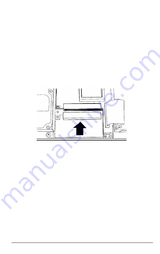
5. Lower the new memory module straight down into the
computer until its connector aligns with the socket on the
system board. Make sure the hole for the attachment screw is
on your left.
6. Carefully press the module straight into the socket. The
connector and socket are designed so they fit together only if
you have aligned them correctly; so do not force them. If you
have trouble, remove the module and try again.
7. When the connector is firmly attached to the socket, replace the
screw on the left side of the module.
8. Replace the keyboard as described on page 4-18.
Connecting Optional Devices
4-15
Содержание ActionNote 4SLC2-50
Страница 1: ......
Страница 3: ...EPSON ActionNote 4SLC2 50 User s Guide ...
Страница 122: ...MNP Command Summary continued Fax Modem B 9 ...
Страница 123: ...AT Register Summary B 10 FaxlModem ...
Страница 124: ...AT Register Summary continued Option Registers S14 Bit mapped configuration register FaxlModem B 11 ...
Страница 125: ...S21 Bitmapped configuration register S22 Bitmapped configuration register B 12 Fax Modem ...
Страница 126: ...S22 Bitmapped configuration register continued S23 Bitmapped configuration register Fax Modem B 13 ...
Страница 128: ...S82 Break handling affected by K commands Result Code Summary Fax Modem B 15 ...
Страница 133: ...Power Source Requirements 120 Volt power source requirements 240 Volt power source requirements Specifications C 5 ...
Страница 154: ...400275800 ...


