background image

SK202 User manual                                                                                                           

Figure 2.


Physical picture of SK202 non


3.  Controlled Auto-negotiation

The Network PHY chip embedded in the SK202 is set in Auto
is able to support 10/100/1000Mbps. In order for the SK202A and
communicate they must operate at the same speed. 
connector of blinks when a 1Gbps communication is established between the local 
and the distant PHY. The Orange LEDs blinks when the communication is at 10Mbps

The  PHYs  on  the  SK202  work  independently  and  each  one 

automatically with the device it is connected to. So two independent negotiations take 
place in parallel. 

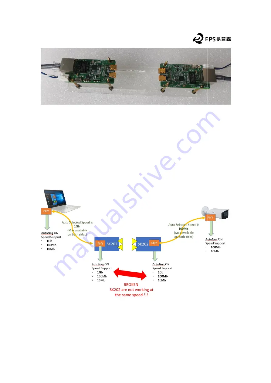
As  a  consequence,  if  the  two  devices,  such  as  a  laptop  and  a  camera,  advertise 

different maximum speeds, the two auto

Figure 3.


For  the  SK202  communication  to  establish  correctly  between  devices 

advertising  different  maximum  speed  capabilities,  the  auto
fastest device has to be controlled.


                                                                                                            2    of    6 

Physical picture of SK202 non-contact connector 

negotiation 

The Network PHY chip embedded in the SK202 is set in Auto-negotiation mode and 
is able to support 10/100/1000Mbps. In order for the SK202A and SK202B to 
communicate they must operate at the same speed. The Green LED on the RJ45 
connector of blinks when a 1Gbps communication is established between the local 

The Orange LEDs blinks when the communication is at 10Mbps

The  PHYs  on  the  SK202  work  independently  and  each  one 

automatically with the device it is connected to. So two independent negotiations take 

As  a  consequence,  if  the  two  devices,  such  as  a  laptop  and  a  camera,  advertise 

rent maximum speeds, the two auto-negotiation results will differ. 


Non controlled auto-negotiation may fail 

For  the  SK202  communication  to  establish  correctly  between  devices 

advertising  different  maximum  speed  capabilities,  the  auto-negotiation  of  the 

stest device has to be controlled. 


negotiation mode and 

SK202B to 

The Green LED on the RJ45 

connector of blinks when a 1Gbps communication is established between the local 

The Orange LEDs blinks when the communication is at 10Mbps


The  PHYs  on  the  SK202  work  independently  and  each  one  negotiates 

automatically with the device it is connected to. So two independent negotiations take 

As  a  consequence,  if  the  two  devices,  such  as  a  laptop  and  a  camera,  advertise 

For  the  SK202  communication  to  establish  correctly  between  devices 

negotiation  of  the 

Содержание SK202A

Страница 1: ...Ethernet replacing note is that both SK202 modules must at the same speed mode as described in section 3 of this document Schematic diagram of using SK202 to connect IP camera SK202 only needs to be connected to the network and power supply but it should be noted that the network negotiation rate of the PC side and the router side are the same If the PC side is a gigabit network the rate automatic...

Страница 2: ...or the SK202A and SK202B to communicate they must operate at the same speed The Green LED on the RJ45 connector of blinks when a 1Gbps communication is established between the local The Orange LEDs blinks when the communication is at 10Mbps The PHYs on the SK202 work independently and each one automatically with the device it is connected to So two independent negotiations take As a consequence if...

Страница 3: ...on is required when the 2 devices do not advertise the same maximum speed capability Alternatively one can introduce a switch operating at the same speed than the slowest device in order to ensure the auto negotiation result will be the same on both sides Auto negotiation result controlled using a switch evaluation method you need to evaluate the impact of SK202 on network transmission it is party...

Страница 4: ...he address as below download php Iperf3 test Schematic diagram with SK202 to connect to the network The network adapters of two PCs Gigabit Ethernet controller IP address of PC A of PC B is set to 192 168 10 3 Please use at least Cat A as a server run command iperf3 server B as client run command iperf3 udp bandwidth 1G client time 100 len 63k 3 will test 100 seconds through UDP protocol with 1G b...

Страница 5: ... below This KOA is a parallelepiped of 22 mm width and 9 mm height The length being the distance between the antennae usually 30 mm Moreover a Safe Area has been defined in orange on the figures below The elements present in this area may have an impact on the millimeter waves ea is a parallelepiped of 60 mm width and height The length being the distance between the antennae usually 20 mm In case ...

Страница 6: ...ness This opening should follow these guidelines The casing must be placed at around 2 7mm from the PCB to ensure a free space of 0 8mm between the Horn antennae body and the ABS housing opening should be minimum 22 mm long and 9 mm wide centered on the 2 antennae but it can be enlarged Should the casing be placed further than 2 7mm from the PCB the opening dimensions will have to be adjusted to p...

Отзывы: