


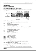


Installation
EP-3WXA/4/4Y
Page 3-6
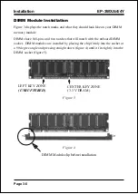
DIMM Module Installation
Figure 3 displays the notch marks and what they should look like on your DIMM
memory module.
DIMMs have 168-pins and two notches that will match with the onboard DIMM
socket. DIMM modules are installed by placing the chip firmly into the socket at
a 90 degree angle and pressing straight down (figure 4) until it fits tightly into the
DIMM socket (figure 5).
Figure 3
CENTER KEY ZONE
(3.3 V DRAM)
LEFT KEY ZONE
(UNBUFFERED)
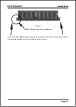
Figure 4
DIMM Module clip before installation
Содержание EP-3WXA
Страница 6: ...EP 3WXA 4 4Y Page Left Blank ...
Страница 14: ...Introduction EP 3WXA 4 4Y Page 1 8 Figure 5 System Block Diagram System Block Diagram ...
Страница 17: ...Installation EP 3WXA 4 4Y Page 3 1 Section 3 INSTALLATION ...
Страница 18: ...Installation EP 3WXA 4 4Y Page 3 2 Figure 1 EP 3WXA 4 4Y Detailed Layout ...
Страница 28: ...Installation EP 3WXA 4 4Y Page 3 12 Page Left Blank ...
Страница 54: ...BIOS EP 3WXA 4 4Y Page 4 26 Page Left Blank ...
Страница 56: ...Drivers Installation EP 3WXA 4 4Y Page 5 2 Page Left Blank ...
Страница 68: ...Appendix EP 3WXA 4 4Y A 12 Page Left Blank ...
Страница 70: ...Appendix EP 3WXA 4 4Y A 14 Page Left Blank ...