


15
EN
198
215
0,5
0,5
35
A
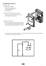
Tabs with mounting holes for screws
A
A
A
A
Dimensions in mm
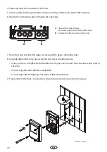
3. Prepare the line openinings in the
housing by breaking the corresponding
plates at the rear or at the bottom side.
4. Insert the supplied bushings into the pre-
pared openings.
5. Draw the connection cables into the con-
trol unit through these openings..
6. Insert the housing into the wall cut-out
and secure it with 4 screws as indicated.
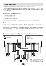
7. Connect power supply and consumers
(see Electrical Installation).
8. Finally mount the front cover back on
the control unit and secure it at the top
with the mounting screw.