X2
F2
F1
L1 L2 L3
N
W
V
U
N
N L
LSG
V1
S1
N
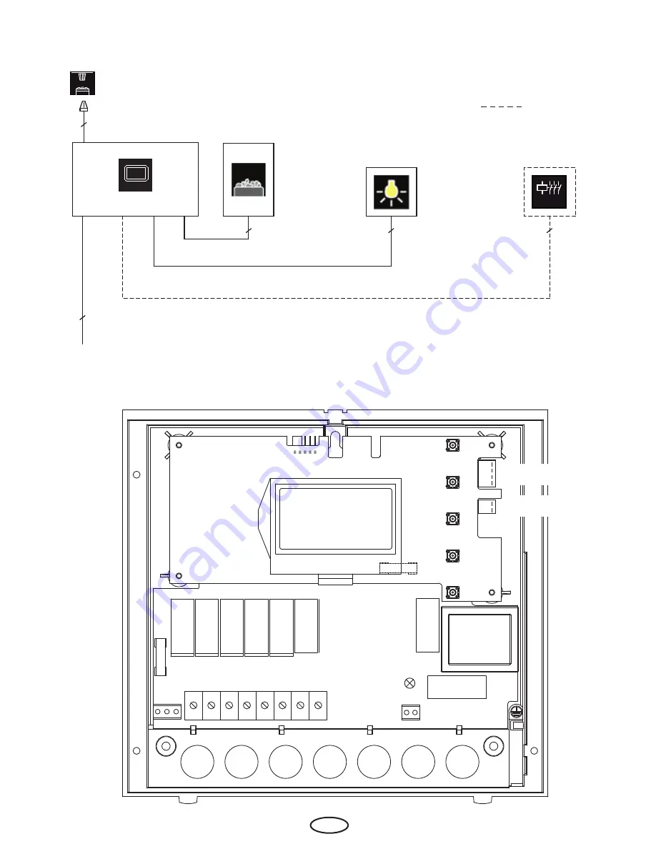
Terminal layout on the main board
Installation diagram
4
3
5
4
5
= optional
400 V 3 N AC 50 Hz
LSG
ECON
Connector for tempera-
ture sensor
Jumper for heating
time limitation
Connection for the 2nd
temp. sensor
14
GB


