9
Electrical connection to the controller
Your electrical contractor will be able to carry out this work without
further clarification according to the connection diagram shown,
and according to the circuit diagram posted in the controller in
question.
Note, however, that for safety reasons, live cables must not be
laid bare on the interior walls of the booth. Therefore, for most
sauna booths, empty tubes are already inserted in the wall
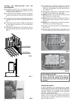
element with the air supply opening for wiring purposes (Fig. 2).
If there are no empty tubes in your booth, drill a hole about 10-
12 mm in size next to the oven, where the cables emerge, and
feed the cables through this hole outwards to the controller (Fig.
2). As with all other connection cables, this cable should also be
protected from damage on the outer side of the booth (supply
lead to the mains and to the booth lighting), e.g. by being laid in
installation tubes or by applying wood covering panels.
Fig. 3
Fig. 2
Connection box-
Distance holder
Connection clamp
Cable screwing
Wall feeding
into a blank tube
Air supply
opening
Fig. 4
Locknut
Fig. 5
Air inlet opening
63 cm
57,5 cm
Wall suspension
Assembly and electrical connection by an electrical
contractor
l
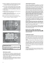
Screw the wall bracket tight per Fig. 5 + 6 centrally over the
air inlet opening with the enclosed chipboard screws.
l
Connect the connection cable per the circuit plan. A circuit plan
is posted on the inside of the connection space cover (Fig. 4).
l
Close the connection box with the cover, distance holder facing
outwards. Use 2 sheet-metal screws for this (Fig. 3).
l
Hang the sauna oven onto the wall bracket with the receptacle
slits on the back wall, and lay it against the distance holder.
Fig. 7.
l
Fix the sauna oven to the wall bracket by means of a sheet-
metal screw through the drilled hole on the back of the oven
(Fig. 8).
Air inlet opening
Fig. 6
min. 10
cm
34 cm
63 cm
Fig. 7
16 cm
Locking screw
Fig. 8
Wall suspension
Содержание Bi-O Tec
Страница 19: ...19...


