background image

21

GB

stallation  or  set-up  in  a  niche,  under  a 
bench or under a sloping roof.

• 

Do not put the sauna heater into operation 
when the air intake is closed.

• 

The cabin lighting and the corresponding 
installation  must  correspond  with  the 
"splash  protected"  version  in  accordance 
with  DIN  EN VDE  0100 T  703. Therefore, 
only VDE-tested sauna light with max. 40 
Watt may be installed in connection with 
the sauna heater. 

• 

  Only  a  locally  certifi ed  electrician 

may  connect  the  sauna  facility  (sauna 
heater, control unit, lighting etc.) to a fi xed 
mains connection.

• 

All electrical installations and all connec-
tion lines that are installed inside the cab-
in must be suitable for an ambient tem-
perature of at least 170 °C. If single-wire 
cables are used as connection lines, they 
must be protected using a fl exible metal 
tube connected to the equipment ground-
ing conductor. Please see the table for the 
minimum cross-section of the connection 
cable and the suitable cabin size in rela-
tion to the power input in kW.

• 

When installing the sauna heater, please 
ensure  that  the  vertical  clearance  be-
tween  the  sauna  heater  upper  edge  and 
the  sauna  ceiling  is  maintained.  Please 
see  also  the  dimensions  diagram  for  the 
clearance between the lower edge of the 

sauna  heater  and  the  fl oor.  On  heaters 
with  bases,  this  clearance  is  maintained 
via the base or legs of the device. 

• 

Please always ensure that the sauna heat-
er  is  never  placed  on  fl ooring  made  of 
fl ammable  material  (wood,  plastic  fl oor-
ing  etc).  Ceramic  tiles  are  recommended 
as fl oor materials.

• 

Floor heating in the sauna cabin increases 
the surface temperature of the fl ooring.

• 

Please  see  the  dimensions  information 
for  the  respective  sauna  heater  for  the 
clearance  between  the  heater  protective 
grating or the bench and other fl ammable 
materials.  The  heater  protective  grating 
must roughly accord with the front height 
of the sauna heater.

• 

Please  also  observe  the  information  and 
instructions provided by the cabin manu-
facturer.

• 

  Please  take  precautions  when 

cleaning components with sharp edges.

• 

Upright heaters need to be fi tted on site 
with  elements  that  prevent  them  from 
overturning.

• 

 Attention:

 Pour the infusion water 

only  on  the  sauna  rocks  and  never  any-
where else.

• 

When  using  your  sauna  in  a  dry 

Finnish mode never add sauna essences or 

Содержание Bi-O Filius

Страница 1: ...1 D MADE IN GERMANY IP x4 Druck Nr 29344341 49 13 Filius Bi O Filius D Montage und Gebrauchsanweisung Installlation and operating instruction GB RU...

Страница 2: ...2 Deutsch 3 English 20 o 37...

Страница 3: ...Filius 9 Technische Daten 9 Mindestabst nde 9 F hlermontage 11 Inbetriebnahme 11 Montage Bi O Filius 12 Technische Daten 12 Mindestabst nde 12 F hlermontage 14 Inbetriebnahme 14 Auswechseln von Rohrh...

Страница 4: ...eliefert hat Beachten Sie dass Sie ein optimales Saunaklima nur dann erreichen wenn die Kabine mit ihrer Zuluft und Abluft das Saunaheizger t und das Steuerger t aufeinander abgestimmt sind Beachten S...

Страница 5: ...A 6 und VDE 0100 Teil 703 2006 2zubeachten Saunaheiz und Steuerger t d rfen nur in Saunakabinen aus geeignetem harz armen und unbehandeltem Material z B Nordische Fichte verwendet werden In der Saunak...

Страница 6: ...stens 170 C geeignet Werden als Anschlussleitung einadrige Leitungen verwendet m s sen diese durch ein biegsames mit dem Schutzleiter verbundenes Metallrohr ge sch tzt werden Den Mindestquerschnitt de...

Страница 7: ...edoch dass stromf hrende Lei tungen aus Sicherheitsgr nden nicht sichtbar an den Kabineninnenw nden verlegt werden d rfen Bei den meisten Saunakabinen sind deswegen bereits in dem Wandelement mit der...

Страница 8: ...er t Ofen Leistungs schaltgetr t erfordrlich zu verwenden mit den Steuerger ten 4 5 kW 3N AC 50 Hz 400 V 3 x 16 4 6 m 35 x 5 cm 5 x 2 5 5 x 1 5 nein ECON D1 ECON D2 ECON H1 ECON H2 EMOTEC DC9000 EMOTE...

Страница 9: ...r Anschluss Absicherung in A f r Kabinen volumen Mindestma der Be und Entl ftung Verbindung Netz Steuerger t Verbindung Steuerger t Ofen Leistungs schaltgetr t erfordrlich zu verwenden mit den Steuerg...

Страница 10: ...rauben 4 x 25 3 St Blechschraube B 4 2 x 9 5 2 St Spanplattenschrauben 1 Einheit Saunasteine DasSaunaheizger tistf reineAnschlussspan nung von 400 V AC 3N ber Saunasteuerger t vorgesehen Die Mindesth...

Страница 11: ...ie end das Abdeckblech wieder auf legen und mit den 4 Schrauben befestigen 7 Das beiliegende Strahlblech wie in Abb 6 gezeigt mit 3 Schrauben 4 2 x 9 5 und die beiden Sicherungsschrauben festschrauben...

Страница 12: ...ntageanweisung Ihres Saunasteuerge r teswirdderF hlerbeidiesemHeizger tmittig ber dem Heizger t an der Kabinenwand 5 cm unter der Decke montiert Abb 7 F hler Inbetriebnahme Nehmen Sie das Saunaheizger...

Страница 13: ...elverschraubung 4 St Blechschrauben 4 x 25 3 St Blechschraube B 4 2 x 9 5 2 St Spanplattenschrauben 1 Einheit Saunasteine DasSaunaheizger tistf reineAnschlussspan nung von 400V AC 3N ber Sauna steuerg...

Страница 14: ...5 Der Anschluss des Verdampfers befindet sich an der linken Seite des Saunaheizge r tes Verfahren Sie zum Anschlie en der Verdampferzuleitung entsprechend dem vor gezeigten Anschluss Abb 5 1 2 Um die...

Страница 15: ...enrand befindliche Bohrung an der Wand Abb 6 oder seitlich wie in Abb 7 gezeigt sichern Abb 6 S i c h e r u n g s schrauben Abb 7 1 9 Abschlie end das Abdeckblech wieder auflegen und mit den 4 Schraub...

Страница 16: ...16 D Auswechseln von Rohrheizk rpern 1 3 2 Abb 1 Abb 2 Abb 3 Abb 4 Abb 5...

Страница 17: ...17 D 2 1 3 4 5 6 180 7 8 9 10 Verdampfer Umbau links rechts Sicherungsschraube Abb 1 Abb 2 Abb 3 Abb 6 Abb 7 3 mm 2 1 6 28 3 mm Abb 4 Abb 5...

Страница 18: ...rsten Gebrauch sp len Sie den Verdampfer bitte durch und bef llen Sie diesen anschlie en d mit frischem Wasser Die Regelung des Verdampfers erfolgt ber das Steuerger t Entweder erhalten Sie einen Feuc...

Страница 19: ...eben Sie hierzu Entkalker f r Haushaltsger te der auch f r Aluminiumgef e tauglich ist nach Angaben des Herstellers dem Wasser im Verdampfer bei Das Wasser Entkalkergemisch ca 10 Minuten zum Kochen br...

Страница 20: ...en Materialen gefertigt Damit Sie lange Freude mit Ihrem Saunaheizger t haben sollten Sie das Ger t warten und pflegen Dabei m ssen Sie darauf achten dass die im Ansaugbereich befindlichen ffnungen un...

Страница 21: ...FI Schalter ab gesichert werden Nach dem heutigen Stand der Technik ist es nicht sinnvoll dampfdichte Rohrheizk rper f r Sauna fen einzusetzen Es kann vorkommen dass die Magnesiumoxidf llung der Heiz...

Страница 22: ...beschreibung anzugeben Diese Garantie umfasst die Verg tung von de fekten Ger teteilen mit Ausnahme normalerVer schlei erscheinungen Bei Beanstandungen ist das Ger t in der Original verpackung oder ei...

Страница 23: ...digte Ware bitte nicht benutzen Lassen Sie sich von dem Transportunternehmen eine schriftliche Best tigung ber den Schaden ausstellen Melden Sie den Schaden bit te umgehend telefonisch bei Ihrem H ndl...

Страница 24: ...tion of the Filius 31 Specifications 31 Minimum clearances 31 Sensor installation 33 Installation of the Bi O Filius 34 Specifications 34 Minimum clearances 34 Sensor installation 36 Replacement of he...

Страница 25: ...pped the goods Please note that you will only be able to achieve anoptimumsaunaclimateifthecabinwithitsair intake and ventilation the sauna heater and the control unit are aligned to each other Please...

Страница 26: ...resin untreatedmaterials e g spruce Only a sauna heater with the appropriate power output may be installed in the sau na cabin Please provide air intake and vent ope nings in each sauna cabin The air...

Страница 27: ...that the vertical clearance be tween the sauna heater upper edge and the sauna ceiling is maintained Please see also the dimensions diagram for the clearance between the lower edge of the sauna heater...

Страница 28: ...ety reasons power ca bles may not be laid visibly on the interior walls of the cabin Most sauna cabins have empty ducts fitted into the wall element with the air intake If no empty ducts are available...

Страница 29: ...nnection control unit heater Power switchgear required to be used with the control units 4 5 kW 3N AC 50 Hz 400 V 3 x 16 4 6 m 35 x 5 cm 5 x 2 5 5 x 1 5 No ECON D1 ECON D2 ECON H1 ECON H2 EMOTEC DC900...

Страница 30: ...onnection mains control unit Connection control unit heater Power switchgear required to be used with the control units 4 5 kW 1 0 kW 3N AC 50 Hz 400 V 3 x 16 4 6 m 35 x 5 cm 5 x 2 5 1pc 5 x 1 5 1pc 4...

Страница 31: ...f sauna stones The sauna heater has been designed for a connection voltage of 400 V AC 3N via a sauna control unit The sauna cabin interior must be at least 1 90 m in height Maintain at least 100 cm c...

Страница 32: ...first undo both screws as shown in fig 3 and pull the terminal block downwards fig 3a Fig 3 Fig 3a Cable screw connection Connection terminal 7 Secure the heater on the sauna wall behind it using 2 sc...

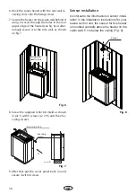
Страница 33: ...trast to the information on sensor instal lation in the installation instructions for your sauna control unit the sensor for this heater is mountedcentrallyabovetheheateronthecabin wall 5 cm below the...

Страница 34: ...a heater 1 accessories bag with 1 pc cable screw connection 4 pcs self tapping screws B 4 2 x 9 5 2 pcs spax screws 1 set of sauna stones The sauna heater has been designed for a connection voltage of...

Страница 35: ...n it with two screws 5 The terminals for connection of the vaporizer are placed on the left side of the heater Make the cable connections to the vaporizer as de scribed above see fig 5 2 In order to c...

Страница 36: ...ver panel back on and secure it with 4 screws A Ansicht A Screws 4 2 x 9 5 Securing screws 8 Screw the supplied reflector shield as shown in pic 5 with 3 screws 4 2 x 9 5 and the 2 Se curing screws Fi...

Страница 37: ...37 D Replacment of heating elements 1 3 2 Fig 1 Fig 2 Fig 3 Fig 4 Fig 5...

Страница 38: ...38 D 2 1 3 4 5 6 180 Vaporizer position change left right Fixation screws Fig 1 Fig 2 Fig 3 7 8 9 10 Fig 6 Fig 7 3 mm 2 1 6 28 3 mm Fig 4 Fig 5...

Страница 39: ...h hazard cannot be removed It is advised not to use those ad ditives apart from the recommended ones by the manufacturer of the oven If additives are put in the water this generally leads to a foaming...

Страница 40: ...stones will re heat suffici ently again Never add more essences or volatile oils than advised on the packaging Never use alcohol or undiluted concentrates Cau tion Fire hazard All sauna heating units...

Страница 41: ...rical units will be protected by this ELCB Under current manufacturing technology it is not reasonable to use heating elements for sau na heaters which do not collect moisture from the surrounding air...

Страница 42: ...el name with detailed description of the fault This guarantee covers defective parts and la bour but not the defects caused by wear and tear In case of complaint please return the equip ment in its or...

Страница 43: ...u the individual case and try for immediate and customer friendly solu tion For economic returns within Germany you will get an RMA number from the manufacturer All returns have to be in the original...

Страница 44: ...44 RU 45 45 46 47 Filius 49 Bi O Filius 50 Filius 51 51 51 53 Bi O Filius 54 54 54 56 57 58 59 60 60 61 61 RMA 62...

Страница 45: ...34 RU DIN EN ISO 9001 2000 110 C 30 40 C 110 C 20 25 85 C 80 90 C...

Страница 46: ...35 RU 8 VDE 0100 49 DA 6 VDE 0100 703 2006 2 5 10...

Страница 47: ...36 RU DIN EN VDE 0100 T 703 40 170 C...

Страница 48: ...37 RU S Guard...

Страница 49: ...4 6 35 x 5 5 x 2 5 5 x 1 5 ECON D1 ECON D2 ECON H1 ECON H2 EMOTEC DC9000 EMOTEC DC9000 DB DL DLF EMOTEC HCS9003 EMOTEC HCS9003 DB DL DLF EmoTouch II PB AF GF 6 0 6 8 7 5 7 10 2000 W 2000 W 2000 W 3x...

Страница 50: ...lius N DIN A 4 5 1 0 3N 50 400 3 x 16 4 6 35 x 5 5 x 2 5 1 5 x 1 5 1 4 x 1 5 ECON H1 ECON H2 EMOTEC HCS9003 EMOTEC HCS9003 DB DL DLF EmoTouch II PB AF GF 6 0 1 5 6 8 7 5 7 10 U V W N PE 2000W 2000W 20...

Страница 51: ...51 RU min 4 cm 40 cm 24 cm 28 cm min 4 cm min 4 cm Filius 400 AC 3N 50 4 5 6 0 7 5 750 180 470 240 8 0 75 1 1 1 4 B 4 2 x 9 5 2 1 400 AC3N 1 90 100 1 2 1 4 2 3...

Страница 52: ...52 RU 4 3 4 4 2 5 2 2 3 3 3 3a 6 2 5 6 5 6 A Ansicht A 4 2 x 9 5 8 7 3 4 2 9 5...

Страница 53: ...53 RU 5 7 5 cm 7...

Страница 54: ...54 RU min 4 cm 47 cm min 4 cm 24 cm 28 cm min 4 cm Bi O Filius 400 AC 3N 50 4 5 6 0 7 5 750 180 470 240 8 0 75 1 1 1 4 B 4 2 x 9 5 2 1 400 AC 3N 1 90 100 1 2 1 4 2 3...

Страница 55: ...55 RU 4 3 4 4 2 5 5 2 2 3 3 3 3a 5...

Страница 56: ...56 RU A Ansicht A 5 6 5 cm 8 6 7 4 2 x 9 5 9 8 3 4 2 9 5 6 7 2 6 7...

Страница 57: ...57 RU 1 3 2 1 2 3 4 5...

Страница 58: ...58 RU 2 1 3 4 5 6 180 1 2 3 4 5 7 8 9 10 3 mm 2 1 6 28 3 mm 6 7...

Страница 59: ...54 RU 4 5 5 1 0 8 4 II Ill 10...

Страница 60: ...44 RU 100 10...

Страница 61: ...45 RU 121471 928 7 495 564 8772 564 8773 995 9744 775 9965 7 495 564 8773 info eos werke ru www eos werke ru EOS Saunatechnik GmbH Schneiderstriesch 1 35759 Driedorf Deutschland 3 2...

Страница 62: ...46 RU RMA RMA RMA 3 1 2 2 RMA...

Отзывы: