Enviro VB09-36 Скачать руководство пользователя страница 33

FORM ET145.18-IOM1 (115) 


ENVIRO-TEC 

33


14.  SYSTEM FLUSHING AND CLEANING  

After the piping system is complete, and prior to connection of 
the refrigeration chassis, the risers should be flushed and 
cleaned to ensure proper start-up and continued efficient 
operation of the system.  

1. 

Ensure that the supply and return riser shut-off valves are 
closed at each unit. 
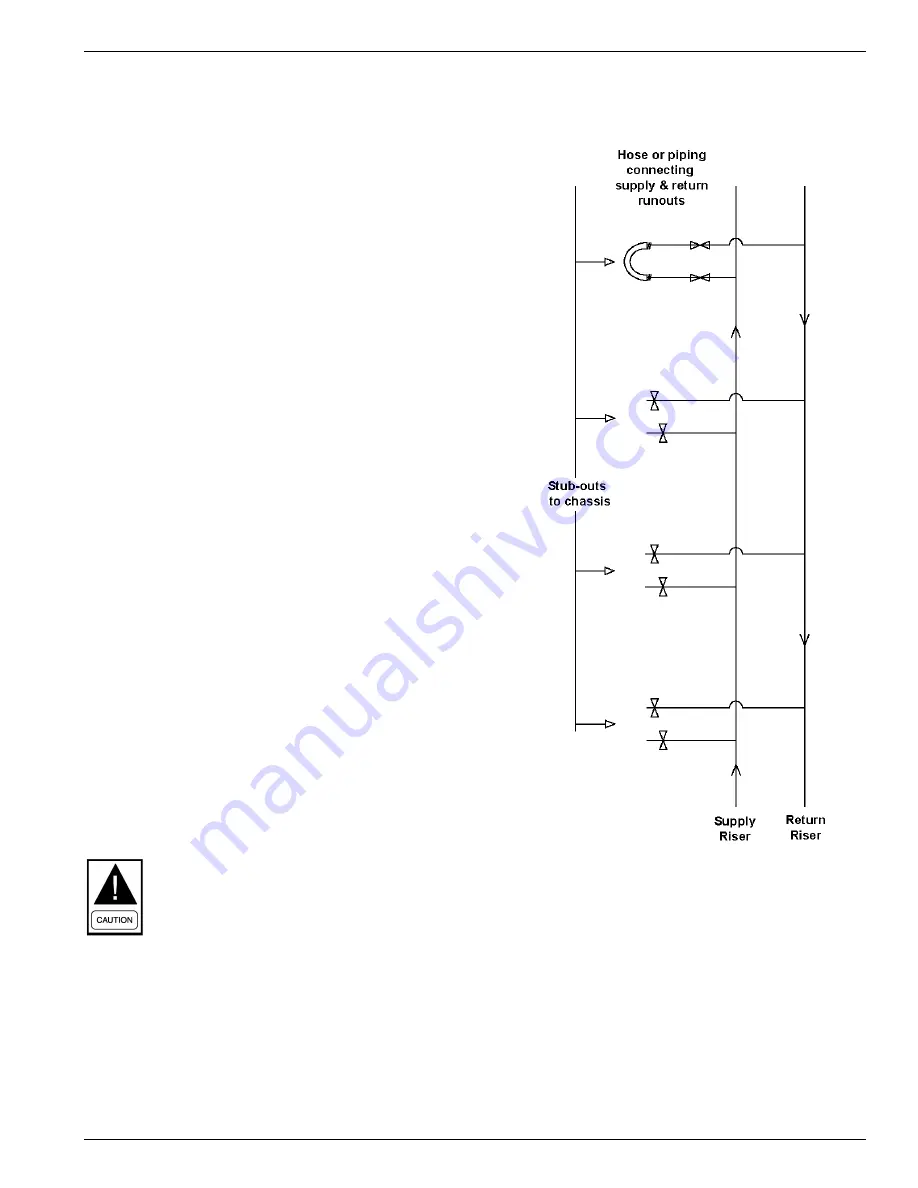
2. 

Using flexible hoses or piping, connect the supply and 
return stub-outs in the unit located at the end of the riser 
run(s). If the building has more than 10 floors, connect the 
supply and return stub-outs in the last two units to divide 
the water flow and reduce pressure drop at the pump. 
(See Figure below) 

3. 

Open the shut-off valves in the units that have had the 
supply and return risers inter-connected. 

4. 

The water circulation system should be filled with clean 
water using the  make-up water supply. The air vents 
should be open during initial filling (Do not allow the 
system to overflow). 

5. 

With the air vents closed, start the circulating pump and 
then crack each air vent to ensure that all air is bled from 
the system. 

(Make-up water must be available in 

sufficient volume to replace the volume occupied by the 
air that is bled off.) 

6. 

When all air is vented, and the water is circulating under 
pressure, the entire system should be checked for leaks. 
Make any repairs as required. 

7. 

Set the loop temperature controls to raise the 
temperature to approximately 85

o

F. Perform a visual 

check for any leaks that may have occurred due to the 
increased heat. Repair as required. 

8. 

Open the drain at the lowest point in the system (make-up 
water flow rate  must be equal to rate of drain bleed). 
Continue to bleed system until water leaving the drain is 
clear, but not less than 2 hours. 

9. 

Completely drain the piping system. 

After the initial Flushing, the system should be chemically 
cleaned. The procedure for re-filling the system, and 
circulating the cleaning solution, is the repeat of the above 
flushing method.  

The services of a professional water treatment company are 
recommended with regards to the type of solution to be used, 
and the duration of the cleaning application.  

Once the cleaning process is complete, shut off the circulating 
pump and completely drain the system. Refill the system with 
clean water in preparation for connection of the refrigeration 
chassis, and system start-up.  

It is strongly recommended a professional water 
treatment company is used to perform on-going 
maintenance of water loop including chemical 
analysis, and if necessary flushing. The water loop 
testing 

should 

be performed at intervals 

recommended by the professional water treatment 
consultant.  It is up to the customer to carry out 
adequate water loop maintenance over the lifespan 
of the units otherwise damage to the units may 
occur.


Содержание VB09-36

Страница 1: ...stallation operations maintenance Supersedes ET145 18 IOM1 513 Form ET145 18 IOM1 115 Issue Date January 21 2015 Vertical Stacked water source Heat Pump model VB VM VS09 36 Cabinet and Model VSCS09 36 Chassis r 410A LD18013 LD18014 ...

Страница 2: ...t is essential that prior to performing any task on this equipment this individual shall have read and understood this document and any referenced materials This individual shall also be familiar with and comply with all applicable governmental standards and regulations pertaining to the task in question SAFETY SYMBOLS The following symbols are used in this document to alert the reader to areas of...

Страница 3: ...RING TO INSTALL UNIT 4 Literature 4 Shipping 4 Inspection Storage 4 Pre Installation 4 Rigging 5 RISER CABINET INSTALLATION 11 Cabinet Placement 11 Supply and Return Piping 12 Hoses 12 ELECTRICAL WIRING 15 Field Installed Power Wiring 15 Field Installed Low Voltage Wiring 15 Optional Surface Mount Thermostat Connection Wiring 15 Optional Remote Mounted Thermostat Wiring 15 Optional ADA Door Mounte...

Страница 4: ...ting to the unit contact the office where you bought the unit You may also refer to the unit rating plate for a contact name B Shipping Cabinets and risers are shipped in one of the following configurations A Risers are attached to cabinet and cabinets are stacked on their side Chassis ships on separate skids B Risers ship loose packaged in boxes and sorted by floor Cabinets ship upright up to 4 p...

Страница 5: ...tion correctly before the equipment is put into operation Never by pass or wire around any safety device Use gloves and protective goggles and where appropriate make sure to have a gas mask close at hand Also use electrical protection equipment and tools suited for electrical operation purposes Personnel must be qualified according to national safety rules and regulations The system should be inst...

Страница 6: ...FORM ET145 18 IOM1 115 ENVIRO TEC 6 FIGURE 1 Cabinet Chassis Model Nomenclature ...

Страница 7: ...FORM ET145 18 IOM1 115 ENVIRO TEC 7 ...

Страница 8: ...c Blower Motor Diameter x Width in 9x4T 9x4T 9x7T 9x7T 10x7T 10x8T 10x8T Motor HP 0 10 0 10 0 17 0 25 0 33 0 33 0 50 ECM Blower Motor Diameter x Width in 9x4T 9x4T 9x7T 9x7T 10x7T 9x8 9x8 Motor HP 0 33 0 33 0 33 0 33 0 33 0 50 0 50 Hi Static ECM Blower Motor Diameter x Width in 9x4T 9x4T 9x7T 9x7T 10x7T 10x8T 10x8T Motor HP 0 33 0 33 0 33 0 33 0 33 0 50 0 50 Filter Quantity Size in 1 14x25x1 1 14x...

Страница 9: ...ation is measured from base of cabinet and does not include stand height FIGURE 2 Cabinet Unit Dimensions Floor Sleeve Dimensions 80 or 88 B A 6 48 4 5 3 50 7 OPTIONAL 24V CONNECTION FOR SURFACE MOUNT REMOTE MOUNTED THERMOSTAT SWITCH PLATE w 2 SPD FAN SWITCH OPTIONAL DISCONNECT FUSES ADA MOLEX CONN 7 8 CONTROL ENTRANCE CHASSIS SERVICE PANEL ELECTRICAL BOX OPTIONAL FRONT SUPPLY OPENING RETURN AIR F...

Страница 10: ...FORM ET145 18 IOM1 115 ENVIRO TEC 10 Note 1 Riser shut off valve is measured from base of cabinet and does not include stand height FIGURE 2A Cabinet Riser Dimensions ...

Страница 11: ...e cabinet into final position 4 Raise the cabinet upright and lower the risers through the floor cut out aligning the risers into the swaged section of the unit on the floor below Take extra care not to scrape or dent risers during positioning The riser tailpiece should insert approximately 2 into the 3 long swaged section of the unit below To ensure correct riser positioning and to compensate for...

Страница 12: ...h NPT type connections and matching risers with NPT shut off valve connections require a special hose kit complete with NPT to NPSH swivel adapter on the shut off valve and chassis connection see Diagram C to mate to factory hoses C HOSES Ensure the correct hose set is matched with the compatible unit size see Table 2 When installing NPSH factory provided hoses installer must follow these procedur...

Страница 13: ... ET145 18 IOM1 115 ENVIRO TEC 13 Diagram A Standard Factory Supplied NPSH Hose Kits and Risers As of June 2013 Diagram B Optional Field Supplied Risers w Factory Supplied NPSH Hose Kits and Shut Off Valves ...

Страница 14: ...FORM ET145 18 IOM1 115 ENVIRO TEC 14 For VB cabinets built prior to June 2013 Diagram C Conversion of NPT to NPSH type fittings VB Units with NPT fittings only ...

Страница 15: ... terminal strip See Figure 4 for typical wiring connections Locate thermostat away from supply drafts Ensure the back of thermostat is sealed and protected from air drafts Short cycling can result in damage to unit RECOMMENDED WIRE SIZE MAX LOW VOLTAGE WIRE LENGTH 20 gauge 50 feet 18 gauge 75 feet 16 gauge 125 feet FIGURE 4 FIELD WIRING DIAGRAM Ensure that the control wiring between the thermostat...

Страница 16: ... and return openings with plastic or cardboard to prevent dust or debris from entering the unit components 3 Install drywall using conventional construction methods Studs or drywall should not be fastened directly to the cabinet surface The spacing of the framing members will be dependent on the return air access and the type quantity of supply air outlets See Figures 7 and 8 4 Install sheetrock a...

Страница 17: ...FORM ET145 18 IOM1 115 ENVIRO TEC 17 FIGURE 7 Critical Return Air Panel with Unit Cabinet Installation Dimensions ...

Страница 18: ...RE 8 Return Air Panel Dimensions Note 1 See Figure 7 for additional R A panel and cabinet installation information FIGURE 9 R A Panel Cross Section Installation at Floor Level Cut away view for standard cabinet with no stand Add stand height to cabinet to obtain correct dimension of R A panel from floor ...

Страница 19: ...FORM ET145 18 IOM1 115 ENVIRO TEC 19 FIGURE 9A Optional Return Air Panel with ADA Mounted Thermostat ...

Страница 20: ...is recommended to apply 1 8 neoprene tape around the perimeter the volume damper prior to inserting into the supply opening See Figure 11 for an example This will assist in reducing noise transmission and air recirculation into unit closet For ducted openings connect the unit supply opening to the supply ductwork using a watertight flexible duct connector This will minimize the transmission of ope...

Страница 21: ...FORM ET145 18 IOM1 115 ENVIRO TEC 21 FIGURE 11 Unit Mounted Supply Grille Installation Dimensions ...

Страница 22: ... installation 5 Top opening size does not change When combined with any other discharge arrangement shallbe be included in determining horizontal opening grille size 6 Openings marked Not Available result in face velocities outside the recommended 300 500 FPM range 7 Hi Static Blower option is not recommended or single horizontal discharge openings with unit mounted supply grille UNIT SUPPLY FACE ...

Страница 23: ...ngs will come with 4 1 4 supply plaster flange B Top Mounted Fresh Air with Motorized Damper Same features as in the top mounted fresh air intake option and including a motorized damper assembly inside the discharge collector box similar to depiction in Figure 12 Damper assembly can be easily removed for servicing see steps below Motorized damper assembly opens during FAN ON operation See Appendix...

Страница 24: ...nit Shown Cabinet Dimensions Model A B C 09 12 17 8 12 15 24 20 12 14 30 36 24 16 18 1 Optional Fresh Air option comes with 4 1 4 R A flange 2 Optional front supply opening comes with 4 1 4 duct flange 3 All other openings come with standard 1 duct flange 4 Left and Right hand versions shown ...

Страница 25: ...use a back up wrench when tightening the hose to the valve fitting Allow the hoses to hang free inside the cabinet Once chassis is slid into place attach the NPSH hoses to the NPSH fittings on the chassis stub outs projecting through the top of the compressor compartment access cover Always use a back up wrench to prevent twisting of the copper water piping within the chassis assembly Refer to the...

Страница 26: ...pply grille return air panel and filter in place 6 Connect hoses to the chassis Ensure that the hoses will not be pinched once the chassis is slid into place 7 Check alignment of the chassis in the cabinet The chassis should be centered in the cabinet opening without touching the flanges on the sides of the cabinet opening 8 Complete the electrical connections to the chassis by means of the two qu...

Страница 27: ...ostat switch to the OFF position The compressor and fan should stop running and the reversing valve should de energize 6 Leave the unit off for approximately 5 minutes to allow for pressure equalization 7 Turn the thermostat to the lowest setting 8 Set the thermostat system switch to the HEAT position The compressor should NOT run 9 Adjust the temperature setting upward until the compressor and su...

Страница 28: ...255 240 225 LOW 255 250 240 230 220 210 HIGH 445 435 425 415 400 385 370 355 340 320 295 LOW 350 345 335 325 315 305 290 HIGH 580 570 560 550 535 520 505 485 465 445 425 LOW 385 380 375 370 365 355 345 335 HIGH 700 690 675 660 635 615 595 575 550 525 495 LOW 450 445 440 435 430 425 HIGH 880 855 835 815 795 770 740 710 680 650 615 LOW 715 710 705 690 670 650 630 605 580 HIGH 1115 1100 1075 1050 102...

Страница 29: ...265 1235 1206 1184 1163 1141 1118 1085 1051 1008 965 913 861 36 1220 840 24 850 571 30 1075 701 15 550 312 18 685 408 External Static Pressure in w g 09 340 220 12 430 290 Unit Size Motor Speed Rated CFM Min CFM ECM TAP 0 0 05 0 1 0 15 0 2 0 25 0 3 0 35 0 4 0 45 0 5 0 55 0 6 0 65 0 7 0 75 1 278 252 226 212 198 189 180 2 342 317 292 276 259 247 236 228 220 214 207 3 411 382 354 334 315 300 286 279 ...

Страница 30: ... be reset by opening and closing the unit mounted disconnect switch If the unit must be reset more than twice on consecutive operating cycles check the unit for a dirty filter abnormal entering water temperature inadequate or excessive water flow or refrigerant circuit malfunction If the unit continues to cutout contact a trained service technician 13 UNIT CONTROLS The control system microprocesso...

Страница 31: ... will re energize the halted compressor Condensate Overflow Switch A Condensate Overflow fault occurs if the Condensate Overflow switch opens continuously for 30 seconds The compressor is shutdown regardless of Minimum Run Time and alarm 15 is set Fan continues operating in its current state The control logs the first incident per compressor request Lockout occurs on the second fault occurrence wi...

Страница 32: ...ive seconds it scans the bus and then assigns itself the first available address starts at 2 It then flashes that address one time Pressing the button two times within five seconds causes the control to flash the address Communication The communication protocol is MODBUS using the RTU method of packet framing at 19200 baud rate TABLE 6 Flash Codes Flash Codes Description On Steady Control Failure ...

Страница 33: ...uld be checked for leaks Make any repairs as required 7 Set the loop temperature controls to raise the temperature to approximately 85o F Perform a visual check for any leaks that may have occurred due to the increased heat Repair as required 8 Open the drain at the lowest point in the system make up water flow rate must be equal to rate of drain bleed Continue to bleed system until water leaving ...

Страница 34: ...FORM ET145 18 IOM1 115 ENVIRO TEC 34 APPENDIX PSC MOTOR WIRING DIAGRAM ...

Страница 35: ...FORM ET145 18 IOM1 115 ENVIRO TEC 35 ECM WIRING DIAGRAM ...

Страница 36: ...FORM ET145 18 IOM1 115 ENVIRO TEC 36 CONTINUOUS FAN WITH ECM WIRING DIAGRAM ...

Страница 37: ...FORM ET145 18 IOM1 115 ENVIRO TEC 37 MOTORIZED DAMPER ECM WIRING DIAGRAM ...

Страница 38: ...st be at least 700 psig high side and 180 psig low side with 550 psig retard All hoses must have a service pressure rating of 800 psig Leak detectors must be designed to detect HFC refrigerants Systems must be charged with refrigerant Use a commercial type metering device in the manifold hose R 410A can only be used with POE type oils POE type oils rapidly absorb moisture from the atmosphere Vacuu...

Страница 39: ...FORM ET145 18 IOM1 115 ENVIRO TEC 39 NOTES ...

Страница 40: ...ennsylvania USA 17405 1592 Subject to change without notice Printed in USA Copyright 2015 ALL RIGHTS RESERVED Form ET145 18 IOM1 115 Issue Date January 21 2015 Supersedes ET145 18 IOM1 513 800 861 1001 www enviro tec com ...

Отзывы: