24
a
Djusting
t
he
P
iLot
f
Lame
:
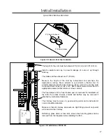
The pilot flow adjustment is set to maximum at the factory and should not need to be adjusted. The pilot
flame should envelope ⅜” to ½” (10 to 13mm) of the thermocouple (see Figure 28). However, should
the need arise, follow Steps 1- 2 below.
Figure 28: Proper Pilot Flame.
Initial Installation
QUALIFIED INSTALLERS ONLY
1. The adjustment screw can be reached through the front of the
unit using a 10 inch flat head screw driver (see Figure 27 for
location on valve).
2. Turn the adjustment screw clockwise to decrease or
counterclockwise to increase pilot flame.


