background image

Fuel Conversion

14

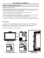
Figure 12: Removing valve 

screw.

Figure 13: Flip valve 

screw.

Figure 14: O-ring on valve screw.

Figure 15. Ignitor assembly 

beside the burner.

d) Insert a 

5

/

32

” or 4 mm Allen wrench into the hexagonal key-way of the screw (see Figure  


    12), rotate it counter-clockwise until it is free and extract it.
e)  Flip the screw (refer to Figure 13).
f)  Using the Allen wrench as shown in Figure 12, rotate the screw clockwise. 

WARNING!

 Do not 

over tighten the screw.

g)  Verify that if the conversion is from NG to LPG, the screw must be re-assembled with the red 

o-ring visible (refer to Figure 14). If the conversion is from LPG to NG, the red o-ring of the 

screw must not be visible.

h)  Re-attach the black protection cap that was removed in step “c)”.  Refer to Figure 11.
i) Reinstall the knob extensions. They are keyed into the notch on the knob. 
j) Reinstall the Valve Cover plate.

8.  Reinstall the burner, porcelain panels, glass beads, 

and glass door. Also refer to 

s

econDary

 I

nstallatIon


-  F

Irebox

  l

Iner


anD

  b

urner

  t

ray

  r

emoVal

  in  your 

Owner’s  Manual.  When  re-installing  the  burner, 

ensure  that  the  burner  to  pilot  hood  relationship 

is similar to what is shown in Figure 15. On some 

units you will need to pay special attention when 

installing  the  burner  that  the  venturi  adjustment 

rod is properly installed into the venturi adjustment 

piece welded to the burner venturi tube

9.  Reconnect the main gas line if it was disconnected 

and open the shut-off valve at the gas line to the 

unit.

10.  Use  a  small  brush  to  apply  a  warm  soapy  water 

solution to all gas connections (use half dish soap 

and half warm water). If a gas leak is present, 

bubbling will occur. Gas leaks can be repaired by using an approved pipe thread sealant or 

approved Teflon tape. NEVER USE AN OPEN FLAME WHEN TESTING FOR LEAKS. 

11.  Reconnect the electrical power to the unit.
12.  Relight the main burner in both the “HI” and “LO” positions to verify proper burner ignition and 

operation and proper flame appearance.

13.  MAKE SURE that the conversion label is installed on or close to the rating label to signify that the 

unit has been converted to a different fuel type. 

Содержание E30G

Страница 1: ...sed WHAT TO DO IF YOU SMELL GAS Open windows extinguish any open flame Do not try to light any appliance Do not touch any electrical switch or use any phone in your building Immediately call your gas supplier from a neighbour s phone Follow the gas supplier s instructions If you cannot reach your gas supplier call the fire department WARNING If the information in this manual is not followed exactl...

Страница 2: ...or in the absence of local codes with the National Fuel Gas Code ANSI Z223 1 NFPA 54 or the Natural Gas and Propane Installation Code CSA B149 1 To prevent injury do not allow anyone who is unfamiliar with the stove to operate it To prevent injury if the pilot or pilot and burners have gone out on their own open the glass door and wait 5 minutes to air out before attempting to re light the stove A...

Страница 3: ...rfaces 11 Removing Valve Cover 12 Fuel Conversion 13 Initial Installation 15 Clearances to Combustibles 15 Minimum Fireplace Size 15 Direct Vent Model 15 Venting Fireplace Inserts 16 Direct Vent Vertical Vent Termination 18 Installing the Unit 19 Zero Clearance Fireplace Installation 20 Electrical Requirements 21 Gas Line Connection 22 Adjusting The Pilot Flame 24 Secondary Installation 25 Optiona...

Страница 4: ...RIES CSA P 4 1 09 TESTING METHOD FOR MEASURING ANNUAL FIREPLACE EFFICIENCY This ENVIRO E30G Fireplace Insert Has been certified for use with either natural or propane gases See rating label Is not for use with solid fuels Is approved for bedroom or bed sitting room IN CANADA must be installed with a permanent wall thermostat for bedroom installations Consult the authority having local jurisdiction...

Страница 5: ...ng label is located on the bottom of the unit behind the front access door Dimensions 5 Figure 1 E30G Exterior Dimensions 27 56 26 56 24 38 14 06 16 25 2 38 17 89 12 05 6 94 6 94 13 73 3 07 15 81 1 30 19 88 18 65 19 61 16 49 2 06 LEFT RIGHT FRONT ...

Страница 6: ...ntemporary Surround Extruded Surround Height 25 635mm 25 635mm 25 635mm Width 39 7 8 1013 mm 39 7 8 1013 mm 39 7 8 1013 mm Trimmable Surround Height Width 38 965mm 46 1168mm Base Shelf Base Shelf Riser Height 1 41mm 2 54mm Width 41 5 8 1057mm 40 1 4 1022mm Depth Bottom 4 112mm Top 3 13 16 97mm 3 11 16 94mm 39 5 8 41 5 8 25 27 3 8 ...

Страница 7: ...l next to the floor because some gas is heavier than air and will settle on the floor WHAT TO DO IF YOU SMELL GAS Do not try to light any appliance Do not touch any electrical switch do not use any phone in your building Immediately call your gas supplier from a neighbor s phone Follow the gas supplier s instructions If you cannot reach your gas supplier call the fire department C Use only your ha...

Страница 8: ... opening and closing Table 2 Normal Sounds Venturi Adjustment Thermopile Thermocouple Warning Incorrect venturi adjustment may lead to improper combustion which is a safety hazard Contact the dealer if there is any concern about the venturi adjustment Figure 5 Adjusting the venturi air setting The venturi adjustment lever is located on the right side of the unit below the door see Figure 5 To avoi...

Страница 9: ...hould be turned to high with the fan OFF for the first four 4 hours This will cure the paint gasket material and other products used in the manufacturing process It is advised that a door or window be opened as the unit will smoke which can irritate some people After the unit has gone through the first burn turn the unit OFF including the pilot and let the unit completely cool Then remove the door...

Страница 10: ...pending on the amount of use the glass should require cleaning no more than two or three times a season Do not clean the glass when it is hot Cleaning The Firebox Remove the glass material Vacuum the bottom of the firebox thoroughly At this time inspect the burner tube for cracking or severe warping If a problem is suspected contact the dealer Replacing The Glass The glass in the fireplace is a hi...

Страница 11: ...te the fireplace with the glass removed CAUTION GLASS MAY SEPARATE FROM DOOR Figure 8 Door Release Figure 9 Door Removal Remove the glass door by placing the hooked end of the door release tool in the hole on the door latch mechanism see Figure 8 and pulling the latch out then over to the center of the unit When the two 2 latches have been released tilt the door forward and then lift up to unhook ...

Страница 12: ... 1 Remove the glass door as shown in Maintenance and Service Glass Door Removal 2 Remove the liners and burner Refer to Secondary Installation Firebox Liner and Burner Tray Removal 3 Then remove the six screws that hold the valve cover in place pointed out in Figure 10 Figure 10 Valve Cover VALVE COVER ...

Страница 13: ... gas supply must be shut off prior to disconnecting the electrical power and before proceeding with the conversion Allow the valve and unit to cool down to room temperature 2 Remove the glass as shown in the Maintenance and Service Glass Door Removal 3 Carefully remove the bottom firebox liner 4 Remove the burner as shown in the Secondary Installation Firebox Liner and Burner Tray Removal 5 Conver...

Страница 14: ...eads and glass door Also refer to Secondary Installation Firebox Liner and Burner Tray Removal in your Owner s Manual When re installing the burner ensure that the burner to pilot hood relationship is similar to what is shown in Figure 15 On some units you will need to pay special attention when installing the burner that the venturi adjustment rod is properly installed into the venturi adjustment...

Страница 15: ...ck Height Depth Fireplace Dimensions 28 711 mm 18 1 2 470 mm 20 508 mm 14 1 4 368 mm NOTE Space must be provided for gas line on left side of unit for servicing purposes 36 914 mm minimum to bottom of unit 12 305mm Mantel 30 762 mm minimum to bottom of unit Combustible Facing Direct Vent WARNING This appliance has been designed to draw room air for proper heat circulation from the sides and bottom...

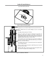
Страница 16: ... and local building codes and has been constructed of non combustible materials Before starting refer to Initial Installation Preparing Your E30G For Installation Please reference the information in Table 4 and Figures 17 and 19 An approved chimney liner and rain cap must be used A throat connector or flashing must be installed to ensure a tight seal top performance safety and efficiency Carefully...

Страница 17: ...imney Every joint in the venting must be secured with three 3 8 x 3 8 HWH sheet metal screws and an appropriate sealant either silicone or stove cement The flue damper can be fully blocked open or removed for installation of the E30 the smoke shelves shields and baffles may be removed if attached by mechanical fasteners The chimney must be clean in good working order and constructed of non combust...

Страница 18: ...3 76mm flex vent over the flue collar and secure with three 3 sheet metal screws evenly spaced Note If fireplace opening is lower than 24 610 mm remove the vent collar plate from the top of the insert see Initial Installation Preparing Your E30G For Installation and connect it securely to the liner as stated in Step 4 Check for tears in the liner at this point 6 Place a bead of high temperature si...

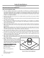
Страница 19: ...stove above the door opening see Figure 21 Slide the collar plate backwards Properly secure the vent collar plate to the flexible vent pipe liner s previously installed in the chimney Be careful not to over stretch the liner s 6 Place the unit part way into the fireplace Connect the gas line to the NPT pipe nipple at the lower left rear of the unit using locally approved methods see Initial Instal...

Страница 20: ...USE IN THIS CONDITION IMPORTANT If the factory built fireplace has no gas access hole s provided an access hole of 1 5 inch 37 5 mm or less may be drilled through the lower sides or bottom of the firebox in a proper workmanship like manner This access hole must be plugged with non combustible insulation after the gas supply line has been installed Cutting any sheet metal parts of the fireplace in ...

Страница 21: ...ds For Electrical Installations or The National Electrical Code ANSI NFPA 70 in the US WARNING The electrical grounding instructions must be followed The fan kit is equipped with a three prong grounding plug for your protection against shock hazard and should be plugged directly into a properly grounded three prong outlet DO NOT cut or remove the grounding prong from this plug CAUTION When servici...

Страница 22: ...per workmanship like manner This access hole must be plugged with non combustible insulation after the gas supply line has been installed A shut off valve is not supplied with this unit but one should be installed The appliance and its shut off valves must be disconnected from the gas supply piping system during any pressure testing where the pressure exceeds psig 3 45 KPa or the valve will be dam...

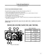
Страница 23: ...move hose and tighten set screw 6 Re install the control panel and knobs Pointer on knobs can be removed and oriented correctly to point at the right location Always check for gas leaks with a soap and water solution after completing the required pressure test NEVER USE AN OPEN FLAME FOR LEAK TESTING 23 Initial Installation QUALIFIED INSTALLERS ONLY 1 2 3 4 5 Item Number Description 1 Control Knob...

Страница 24: ... should the need arise follow Steps 1 2 below Figure 28 Proper Pilot Flame 3 8 1 2 10 13mm Thermocouple Proper Flame Adjustment Initial Installation QUALIFIED INSTALLERS ONLY 1 The adjustment screw can be reached through the front of the unit using a 10 inch flat head screw driver see Figure 27 for location on valve 2 Turn the adjustment screw clockwise to decrease or counterclockwise to increase ...

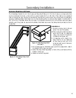
Страница 25: ...nel options and it may also be used with the E30G Trimmable Surround The Base Shelf and Riser are sold separately Installation 1 If unit is running turn it off and allow it to cool completely 2 When using more than one riser each level must be attached using nine 9 8 T 20 screws provided see Figure 29 3 If installing with riser s the Base Shelf is to be fastened to the riser s with one T 20 screw ...

Страница 26: ...ide the fireplace opening for a cleaner appearance 4 Cut along the preferred line from direct measurements of offset and remove any sharp edges 5 The panel can be touched up with a high temperature metallic black paint available from your dealer INSTALLATION 1 Install the two Trimmable Panel brackets onto the E30G unit using a T 20 Torx screwdriver See Figures 31 and 32 for the screw installation ...

Страница 27: ...s are secure before releasing the surround The surround should be wiped with a damp cloth periodically Screws can be tightened for a more permanent install REMOVAL Lift the surround straight up in order to unhook the notch on the hooks from the screws Pull the surround away from the fireplace Place the surround where it will not be damaged Figure 36 Screw Locations Figure 37 Screw and Hook Close U...

Страница 28: ...iners and the burner tray NOTE Follow the steps in the reverse order for reassembly Secondary Installation 28 Figure 41 Remove the clips which secure the side panels and then pull the bottom of the panels towards the center of the firebox Figure 42 Remove the rear brick panel by pulling it forward off the ledge Figure 38 Remove the six T20 screws and then remove the bottom panel by lifting up Figu...

Страница 29: ...stallation Installing the Glass Beads Pour the glass beads into the tray and evenly distribute over the entire tray Ensure that the pilot box remains clear of any glass Figure 43 Burner tray with glass installed 29 ...

Страница 30: ...heck thermocouple voltage at valve It must be greater than 5 mV If low replace thermocouple Air in gas line pilot dies while knob is depressed Bleed line Check gas line pressure Contact dealer Burners will not remain lit Problem with thermopile circuit Check gas line pressure Check for flame impingement on thermopile If low see Pilot will not remain lit Check thermopile for minimum of 300 mV when ...

Страница 31: ...t Shield 50 2550 7 Valve Extension C W Knob Long 50 2501 8 FPI Fan Controller 69 5V 115V W FS Knob EF 045 9 Fan Controller Knob W Decal EC 040 10 Control Panel C W Decal 50 2356 11 S I T Piezo Ignitor EC 023 12 Control Panel Bushings Set 2 50 2352 13 Control Panel Knobs Set 2 50 2355 14 Burner Tray 50 2551 15 Door Complete 50 2505 16 Glass C W Gasket 21 75 X 13 575 50 2506 17 Dual Bulb Door Gasket...

Страница 32: ...tallic Black Touch Up Paint PAINT 12 MB 25 Pilot Assembly 50 2513 Reference Number Option Description Part Number 26 Regular Surround Panel 50 2418 27 Contemporary Surround Panel 50 2419 28 Extruded Surround Panel 50 2420 29 Trim able Surround Panel 50 2422 30 Base Shelf 50 2424 31 Base Shelf Riser 50 2425 32 Four Sided Surround 50 2484 33 Four Sided Trimmable Panel 50 2485 34 Safety Screen 50 249...

Страница 33: ...Parts Diagram Components 33 2 1 3 4 24 23 6 21 25 22 20 18 14 19 7 9 8 5 10 11 12 13 17 16 15 ...

Страница 34: ...Parts Diagram Options 34 27 33 28 29 31 32 30 26 34 ...

Страница 35: ...must be provided by you or the dealer including serial number Exclusions An expanded list of exclusions is available at www enviro com help warranty html This warranty does not cover Damage as a result of improper usage or abuse Damage caused from over firing due to incorrect setup or tampering Damage caused by incorrect installation To the Dealer Provide name address and telephone number of purch...

Страница 36: ..._______________________ MODEL ___________________________________ SERIAL NUMBER ___________________________ DATE OF PURCHASE _____________ dd mm yyyy DATE OF INSTALLATION ___________ dd mm yyyy DIRECT VENT B VENT NATURAL GAS NAT PROPANE LPG INLET GAS PRESSURE _________in WC MAIN BURNER ORIFICE __________ DMS PILOT ORIFICE _________OR________in diam INSTALLER S SIGNATURE ___________________________...

Отзывы: