


22
40
39
38
37
36
35
34
33
32
31
30
29
28
27
26
25
24
23
22
21
20
19
18
17
16
15
14
13
12
11
10
9
8
7
6
5
4
3
2
1
1 2
3 4 5 6 7 8 9 10 11 12 13 14
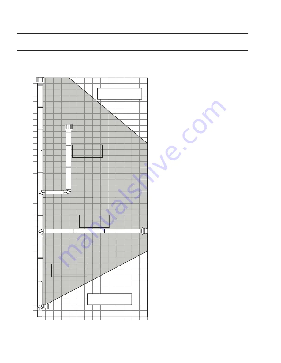
HORIZONTAL RUN
ft
VER
TIC
AL RISE
INSTALLATION
PROHIBITED
INSTALLATION
PROHIBITED
No Restrictor
Required
Restrictor
Setting #1
Restrictor
Setting # 2
Figure 26:Possible Vent Confi gurations for
Vertical and Horizontal Terminations.
Initial Installation
QUALIFIED INSTALLERS ONLY
a
LLowabLe
v
ent
c
onfiguRations
:
Figures 26 show the range of possible vent confi gurations for vertical and horizontal terminations. Any
layout that remains within the shaded areas is acceptable. Having the fewest number of elbows is ideal,
as they tend to disrupt air movement. Using 45˚ elbows is preferable to using 90˚ elbows. Also, a
shorter vent system will perform better
than a longer one.
The total length of
horizontal vent pipe can not exceed
14 feet (4.27m) with one elbow in
the horizontal plane, and the total
vent length can not exceed 44ft
(13.4m).
Any combination of rise and
run can be used as long as it lays within
the shaded area (a total of two (2) 90
˚
elbows or four (4) 45
˚
elbows can be
used. In addition to what is shown, if a
90
˚
elbow is used in the horizontal plane,
3 feet (91.4cm) must be subtracted from
the allowable horizontal run (for each 45
˚
elbow, 1½ feet must be subtracted).
Note
: The air restrictor (supplied with
the unit) is required for vertical venting
runs of 10ft (3.05m) or taller. See
a
ir
r
eStrictor
S
ettinGS
for more information
Содержание Berkeley-Nova
Страница 39: ...39 Parts List 21 1 24 25 2 9 5 14 13 19 20 23 3 11 12 4 6 10 7 8 18 16 22 17 27 15 26...
Страница 42: ...42 Notes...