envea AirFlow P Скачать руководство пользователя страница 15

15

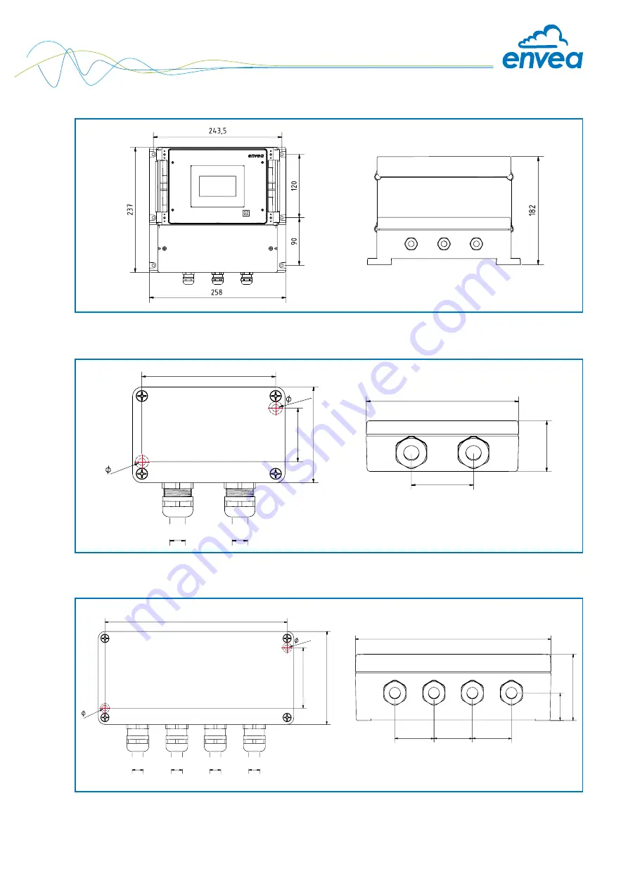
Fig. 10: Dimensions C1 box

Fig. 11: Dimensions C3 box

max.

13 mm

max.

13 mm

50 mm

125 mm

113 mm

52 mm

80 mm

57 mm

4,8 mm

4,8 mm

5 m

m

163 mm

175 mm

35 mm

35 mm

35 mm

23,5 mm

57 mm

52 mm

80 mm

max.

13 mm

max.

13 mm

max.

13 mm

max.

13 mm

5 mm

Fig. 9: Dimensions of the MSE 300-FH

Содержание AirFlow P

Страница 1: ...OPERATING INSTRUCTIONS AirFlow P VOLUME CURRENT MEASUREMENT ENVEA Process GmbH Gutedelstra e 31 79418 Schliengen GERMANY Tel 49 0 7635 827248 0 info process envea global www envea global...

Страница 2: ...ta has been changed the change will only be taken into account when you exit the complete menu structure and answer Yes when asked if you wish to save the changes Afterwards the start page appears If...

Страница 3: ...ect the correct COM port and connect to the device using the read device button Select correct sensor In the menu System under Sensor 8 2 5 or 7 2 5 the correct sensor must be selected After selecting...

Страница 4: ...al connection 17 5 1 Terminal layout MSE 300 DR 17 5 2 Terminal layout MSE 300 DR2 18 5 3 Terminal layout MSE 300 FH 19 5 4 Terminal layout of C Boxes 20 5 5 Electrical connection sensor 21 6 Operator...

Страница 5: ...or mounting Sensor consisting of 2 x antenna 1 x electronic box Assembly instructions C1 or C3 Box optional Sensor C1 box MSE 300 FH max 300 m 1 24 V 2 GND 3 A 4 B S Earth C1 Box optional 16 24 V 15 G...

Страница 6: ...4 B Shield The system can be equipped with up to three sensors Accordingly different C Boxes C1 C3 are used Fig 3 Overview with C3 Box and MSE 300 FH Fig 4 Overview with C3 Box and MSE 300 DR C3 box...

Страница 7: ...l signal The signals from the two antennas are further processed in the sensor s electronics box The electronics box of the sensor correlates the received signals of both antennas with each other and...

Страница 8: ...t must be worn to avoid injuries caused by possible sharp edges on the measuring device When using a cable with more than 4 cores unused open cores may cause sparking Failure to comply with the specif...

Страница 9: ...sion electric shock or damage due to incorrect or non existent earthing Incorrectly connected equipotential bonding can result in charges that can lead to explosions in an explosive atmosphere electri...

Страница 10: ...ditional information concerning product reliability please contact ENVEA Process GmbH 3 7 Storage conditions Observe the following instructions during storage To ensure shock resistance store in origi...

Страница 11: ...rizontal or sloping pipelines the installation should be carried out from above Depending on the geometry and size of the line to be monitored several sensors are used From a line size of 1500 mm 2 se...

Страница 12: ...act with the opposite line wall or any other device This would short circuit the electrodynamic signal To prevent this condition the length of the antennas can be shortened to a minimum length of 120...

Страница 13: ...alibration of the sensor The two antennas are then screwed in tightly The connections are to be checked for tightness appropriate sealing tape is to be used Once both antennas are installed the electr...

Страница 14: ...14 4 6 Dimensions 118 35 23 90 Fig 7 Dimensions of the MSE 300 DR Fig 8 Dimensions of the MSE 300 DR2...

Страница 15: ...1 Dimensions C3 box max 13 mm max 13 mm 50 mm 125 mm 113 mm 52 mm 80 mm 57 mm 4 8 mm 4 8 mm 5mm 163 mm 175 mm 35 mm 35 mm 35 mm 23 5 mm 57 mm 52 mm 80 mm max 13 mm max 13 mm max 13 mm max 13 mm 5 mm F...

Страница 16: ...16 Fig 14 Dimensions AirFlow P sensor 120 0 220 00 100 0 466 7 160 8 Fig 12 Dimensions G 1 double socket Abb 13 Dimensions G 1 double screw on socket for thin channels G 1 100 mm 43 mm 80 mm 226 mm...

Страница 17: ...le of type lflex Classic 110 CY is recommended The cable should be four wired twisted and shielded A minimum cable cross section of 0 75 mm2 should be observed For distances more than 150 m the cable...

Страница 18: ...Current output 4 20 mA 2 Current output 4 20 mA 2 Current output 4 20 mA 1 2 3 4 5 9 6 10 7 11 8 12 Sensor connection Cable 1 Power supply 24 V Sensor connection Cable 2 Power supply 0 V Sensor conne...

Страница 19: ...ut Current input I out1 Current output Current output Na Not used Na Not used Na Not used Na Not used Min Max Relay NO Floating change over contact NO make contact C Floating change over contact C com...

Страница 20: ...ox is absolutely necessary as soon as an averaging of up to three sensors at one measuring point is to take place Evaluation unit Sensor 1 Sensor 2 Sensor 3 M20 M20 Fig 18 Electrical connection C3 Box...

Страница 21: ...21 5 4 Electrical connection sensor PIN 1 Power supply PIN 2 Power supply PIN 3 Modbus A PIN 4 Modbus B PIN 5 Shield Fig 20 Electrical connection of the plug connector 1 2 3 4 5...

Страница 22: ...ons The following overview shows the differences between the variants Function MSE 300 FH MSE 300 DR MSE 300 DR2 Menu system via PC software yes yes yes via display yes no yes Multiple current outputs...

Страница 23: ...2 0 ProSens M Sens 2 M Sens 3 M Sens WR M Sens WR2 Afterwards the start page appears The start page in the display shows the following values Name AirFlow P a freely selectable text describing materi...

Страница 24: ...re and answer Yes when asked if you wish to save the changes For reasons of clarity no further presentation of the display menus is provided The display representations are derived directly from the m...

Страница 25: ...ty even An RS 485 to USB adapter can be purchased from ENVEA Process A standard USB A B cable is supplied for the USB connection to the DIN Rail version The USB connection is a point to point connecti...

Страница 26: ...st be confirmed by checking the selection Overwrite baud r address In addition with the PC software the parameters of the Evaluation unit can be saved in a file Save configuration the parameters of th...

Страница 27: ...and will not be explained in the following document If multiple sensors are used this will only affect the application of sensors and the monitoring of sensors by the Evaluation unit The presence of m...

Страница 28: ...Evaluation units which are not preconfigured for a multi sensor system always have address 1 only sensor 1 will be activated Sensors which are inserted afterwards in a system must be adjusted by means...

Страница 29: ...1 3 Time unit Selection h min s Time base for air flow calculation 1 4 Decimal point Selection Number representation and 0000 0 000 00 00 000 0 decimal point accuracy in the measurement menu 1 5 Set...

Страница 30: ...he measured speed 2 2 Calibration filter s Input 1 s 9999 s Filter time for recording the raw value during calibration The measured over the set period of time measured over the set period of time are...

Страница 31: ...ents are scaled by this factor 2 2 Calibration filter s Input 1 9999 Filter time for recording the raw value during calibration It would be made an average out of the measured RAW values 2 3 Calibrati...

Страница 32: ...sensor 2 2 7 2 P1 value Input measurement Output measurement in the selected mass time unit 2 7 3 P1 calibration Transfer raw value Transfer of the current raw value filtered from the mass flow with t...

Страница 33: ...nues for as long as the measurement is not smaller or larger than the limit value plus or minus hysteresis 3 5 Operation mode Selection NC the relay is closed Working closed as long as no alarm is act...

Страница 34: ...at the output signal 4 5 Analog output 1 Submenu 4 5 1 Calibration 4 mA Selection Key functions can be used to set the Setting the output current current and equalise it to the receiver side 4 5 2 Ca...

Страница 35: ...output of 4 mA is set to the background noise of the measuring point If the background noise decreases due to process changes sensor wear or other ageing effects a signal of less than 4 mA can be out...

Страница 36: ...ng 5 1 Function Selection OFF Cleaning OFF No pulse output Cleaning Option for actuation of a solenoid value for pneumatic air flushing 5 2 Pulse period Input 1 s 600 s Duration between two pulses 5 3...

Страница 37: ...20 mA signal must be read in via Set input current key functions 6 3 Correction Selection Current input correction activated Current input OFF OFF Correction deactivated 6 4 P1 input Input 4 mA 20 mA...

Страница 38: ...sensor 1 7 2 5 Flow direction Selection Possibility of inversion in case of wrong forward reverse installation sensor 2 7 2 6 Flow direction Selection Possibility of inversion in case of wrong forward...

Страница 39: ...alizer value is hidden 7 3 4 Backlight Input 0 min 99 min Display lighting in minutes 0 Permanent lighting 99 Time selection for lighting 7 3 5 Contrast Input 0 100 In the event of an inadequate displ...

Страница 40: ...if necessary Only by instruction of trained personnel from ENVEA Process If a detailed error analysis is necessary you can use the PC software by clicking on Sensor Dump to save a copy of all ModBus r...

Страница 41: ...sensor shows the process indicator P1000 the sensor has been installed against the direction of flow Using function 7 2 4 flow direction the measuring direction can be rotated and the measurement can...

Страница 42: ...utput 2 3 are provided for the MaxxFlow HTC All other sensors output their 4 20 mA signal to analogue output 1 Pulse output In 5 Pulse output there is an option to use different pulses A cleaning puls...

Страница 43: ...which can be prevented by optimising the sensor or delivery parameters Process indicators are not sensor errors but rather provide information about optimisation potential at the measuring point Disp...

Страница 44: ...Calibration shifted by abrasion on the sensor head Perform a recalibration Switch output relay chatters Hysteresis too low Increase hysteresis Check for fault caused by external consumer Do not open...

Страница 45: ...signal Check parameters set fixed speed or replace sensor PROC P0020 2 4 20 mA Inverted input signal on a channel Check parameters set fixed speed replace sensor PROC P0040 2 4 20 mA Measurement rang...

Страница 46: ...r consumption 20 W 24 VA Protection category IP65 to EN 60 529 10 91 Ambient operating temperature 10 45 C Dimensions 258 x 237 x 174 W x H x D Weight Approx 2 5 kg Interface RS 485 ModBus RTU USB Cab...

Страница 47: ...A Max rated load 230 V AC 250 VA Max breaking capacity DC1 3 110 220 V 3 0 35 0 2 A Min switching load 500 mW 10 V 5 mA Data backup Flash memory Pulse output Open Collector max 30 V 20 mA MSE 300 DR2...

Отзывы: