background image


Capable of recording 256 events 

User password 

Changing primary and secondary values of current and voltage transformers 

Making measurements on 5 different connection type systems: 3 Phase 4 W ires, 3 
Phase 3 Wires, 3 Phase Aron, 3 Phase 4 W ires Balanced, 3 Phase 3 Wires Balanced 

Contrast setting 

Backlight setting 

Demand and integration time setting 

Daylight savings time switching 


Applications


MPR-3 Series devices are microprocessor-based devices which are designed to measure all parameters 
of an electrical network, calculate the consumption values and display these on its LCD screen. Events 
like interruptions, time and settings changes, reset operations will be recorded in real-time thanks to its 
internal flash memory and Real Time Clock chip. These events then can be accessed and monitored 
remotely via RS-485 line with Modbus RTU protocol.


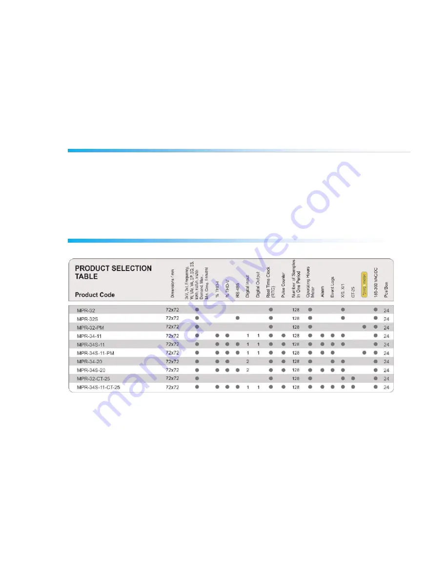
MPR-3 Series Products 


Содержание MPR-32

Страница 1: ...ALLATION 10 3P4W 3 Phase with Neutral Connection 10 3P3W 3 Phase without Neutral Connection 11 Aron without Neutral Connection 11 3P4W BLN 3 Phase Balanced with Neutral Connection 12 3P3W BLN 3 Phase...

Страница 2: ...3 Input Parameter Settings 34 Output Parameter Settings 35 Pulse Output Settings 36 Operating Hours Settings 38 Alarm Settings 39 Reset Settings 42 System Settings 44 Reporting Screen 47 Reading the R...

Страница 3: ...in case of any problems with your device Device is only for panel mounting F Type fuse must be used and its current limit must be 1 A The manufacturing company is not responsible for the consequences...

Страница 4: ...0 VAC VDC Tolerance up to 10 Tolerances up to 10 Supply Frequency 50 60 Hz Maximum Measuring Current 5 5 A Maximum Measuring Voltage 480 VAC VLL Operating Temperature 10 55 C Storing Temperature 20 70...

Страница 5: ...er Total Reactive Power Total Apparent Power Total Cos Total Power Factor Total Harmonic Distortion for Current Total Harmonic Distortion for Phase Phase Voltages Total Harmonic Distortion for Phase N...

Страница 6: ...gration time setting o Daylight savings time switching Applications MPR 3 Series devices are microprocessor based devices which are designed to measure all parameters of an electrical network calculat...

Страница 7: ...ut On models with two inputs they are used as IN1 and IN2 inputs Out Digital Output In Digital Input 4 RS 485 Input 5 Current Terminals Back Panel of the model with one input one output K1 1st Phase C...

Страница 8: ...e network is operating 2 Indicates that the displayed value is negative 3 Indicates that the measurement is inductive or capacitive 4 Indicates that the digital output is active 5 Indicates that the p...

Страница 9: ...I F above the button it is used to browse between voltage current and frequency measurement screens While on measuring screen As seen on the symbols Event below the button event screen is reached when...

Страница 10: ...ement there for it must be used with external current transformers If the device will be use with other analysers on the same panel it is recommented that the device will be the last point on the curr...

Страница 11: ...Neutral Connection For this configuration three voltage connections and three current connections are used Aron without Neutral Connection For this configuration three voltage connections and two curr...

Страница 12: ...vice shows the same current value which is measured from the first phase for the unconnected phases 3P3W BLN 3 Phase Balanced without Neutral Connection For this configuration three voltage connection...

Страница 13: ...he device On the following table possible connection errors that may be encountered during connection test and their corresponding error codes that are displayed on the device screen Test Error Code T...

Страница 14: ...t screens which can be accessed by pressing the related buttons are explained in this section Current Voltage and Frequency Screens BUTTON NAME DISPLAYED MEASUREMENT SCREEN BACK VIF VOLTAGE L N BUTTON...

Страница 15: ...IF CURRENT BUTTON NAME DISPLAYED MEASUREMENT SCREEN BACK VIF FIRST HOUR COUNTER BUTTON NAME DISPLAYED MEASUREMENT SCREEN BACK VIF SECOND HOUR COUNTER Power and Power Factor Screens BUTTON NAME DISPLAY...

Страница 16: ...NT SCREEN DOWN P PF ACTIVE POWER BUTTON NAME DISPLAYED MEASUREMENT SCREEN DOWN P PF REACTIVE POWER BUTTON NAME DISPLAYED MEASUREMENT SCREEN DOWN P PF APPARENT POWER BUTTON NAME DISPLAYED MEASUREMENT S...

Страница 17: ...MEASUREMENT SCREEN DOWN P PF COS Energy and Harmonics Screens BUTTON NAME DISPLAYED MEASUREMENT SCREEN UP THD L N BUTTON NAME DISPLAYED MEASUREMENT SCREEN UP THD L L BUTTON NAME DISPLAYED MEASUREMENT...

Страница 18: ...SCREEN UP Import Active Energy BUTTON NAME DISPLAYED MEASUREMENT SCREEN UP Export Active Energy BUTTON NAME DISPLAYED MEASUREMENT SCREEN UP Import Reactive Energy BUTTON NAME DISPLAYED MEASUREMENT SC...

Страница 19: ...T SCREEN UP Time BUTTON NAME DISPLAYED MEASUREMENT SCREEN UP Date Minimum Maximum and Demand Screens To see the minimum and maximum values of current and voltage first select the relevant screen with...

Страница 20: ...Phase Neutral Voltage BUTTON NAME DISPLAYED MEASUREMENT SCREEN SET MAX MIN MIN Phase Neutral Voltage BUTTON NAME DISPLAYED MEASUREMENT SCREEN SET MAX MIN MAX Phase Phase Voltage BUTTON NAME DISPLAYED...

Страница 21: ...BUTTON NAME DISPLAYED MEASUREMENT SCREEN SET MAX MIN DEMAND I BUTTON NAME DISPLAYED MEASUREMENT SCREEN SET MAX MIN MAX DEMAND I BUTTON NAME DISPLAYED MEASUREMENT SCREEN SET MAX MIN MAX I 21...

Страница 22: ...nd demand values of power parameters first select the relevant screen with P PF button Afterwards you can display the following screens with MAX MIN DEMAND BUTTON NAME DISPLAYED MEASUREMENT SCREEN SET...

Страница 23: ...BUTTON NAME DISPLAYED MEASUREMENT SCREEN SET MAX MIN MAX P BUTTON NAME DISPLAYED MEASUREMENT SCREEN SET MAX MIN MIN P BUTTON NAME DISPLAYED MEASUREMENT SCREEN SET MAX MIN MAX Q 23...

Страница 24: ...BUTTON NAME DISPLAYED MEASUREMENT SCREEN SET MAX MIN MIN Q BUTTON NAME DISPLAYED MEASUREMENT SCREEN SET MAX MIN DEMAND S BUTTON NAME DISPLAYED MEASUREMENT SCREEN SET MAX MIN MAX DEMAND S 24...

Страница 25: ...y programming menu is reached If PIN feature is not activated programming menu is reached directly Password for the device is 1234 as factory default Device Installation Settings In order for the devi...

Страница 26: ...tion Type Setting 1 By using UP DOWN buttons select your network connection type as 3P4W 3P3W ARON 3P4W Balanced or 3P3W Balanced 2 For unbalanced systems 3P4W or 3P3W should be selected 3 Press the S...

Страница 27: ...next step VT Primary Value 1 Enter the primary value of your VT by using SET and UP DOWN buttons 2 You can approve a digit value by pressing the SET button 3 After entering the necessary value Press t...

Страница 28: ...requency Value Selection 1 By using UP DOWN buttons select your nominal network frequency as 50 Hz or 60 Hz 2 After selecting the necessary value Press the SET button and go to the next step Nominal O...

Страница 29: ...using SET and UP DOWN buttons 2 You can approve a digit value by pressing the SET button 3 After entering the correct date Press the SET button and go to the next step Hour Setting 1 Enter the time by...

Страница 30: ...ET button 3 When exiting from the menu with the BACK button don t forget to save the changes Backlight Setting There are three settings for the backlight of the device 1 Always ON 2 Always OFF 3 Autom...

Страница 31: ...changes Time Settings Hour Setting The time of the device s RTC Real Time Clock module can be set in hours minutes and seconds To set the time follow these steps 1 Press the SET button while on Setup...

Страница 32: ...ur time zone in 30 minutes increments by using UP DOWN buttons 5 Press the SET button after you re finished with selection 6 When exiting from the menu with the BACK button don t forget to save the ch...

Страница 33: ...with the BACK button don t forget to save the changes RS 485 Baudrate Setting RS 485 communication speed of the device can be set to one of the following options 1 2400 baud 2 4800 baud 3 9600 baud 4...

Страница 34: ...Settings One of the operating types is selected for the input of the device 1 Digital Input When this option is selected the device detects the logic level on the input 2 Generator Input When this opt...

Страница 35: ...low the limit value When the alarm condition is resolved output returns to logic 1 3 Output as Remote Control When this option is selected the user can change the output of the device from logic 1 to...

Страница 36: ...Output is selected the device can create pulses for import or export active energy according to the increments listed below Import or export energy can be selected as the source 1 Wh 10 Wh 100 Wh 1 kW...

Страница 37: ...ION is displayed 2 Enter the duration in seconds with 0 01 second increments with UP DOWN buttons 3 Exit from the menu when selection is complete 4 When exiting from the menu with the BACK button don...

Страница 38: ...while HOUR COUN PARA is displayed 2 Select the parameter with UP DOWN buttons 3 Press the SET button Afterwards the limit value is selected When the parameter exceeds this limit value hour counter wi...

Страница 39: ...exiting from the menu with the BACK button don t forget to save the changes Alarm Parameter Selection Alarm parameter is selected by following these steps 1 Press the SET button while Alarm Setup is...

Страница 40: ...Higher than 3 When In window or Out window options are selected high and low limit values are entered 4 When Higher than option is selected a high limit value is entered When Lower than option is sele...

Страница 41: ...or the alarm is entered in this menu 1 While Alarm Enable is selected find Alarm Hyst menu with UP DOWN buttons 2 Press the SET button Enter the hysteresis value for the alarm as with UP DOWN buttons...

Страница 42: ...eset Settings Users can reset the minimum maximum demand values that the device has stored Resetting Maximum Values 1 Select Maximum under Reset menu and press the SET button 2 Press the SET button wh...

Страница 43: ...Demand under Reset menu and press the SET button 2 Press the SET button while Reset de is displayed and select YES option with UP DOWN buttons 3 Press the SET button 4 When exiting from the menu with...

Страница 44: ...e changes Resetting Hour Counter Value 1 Select Hourcntr under Reset menu and press the SET button 2 Press the SET button while Reset Hour is displayed and select YES option with UP DOWN buttons 3 Pre...

Страница 45: ...ng option under System Menu Press the SET button 2 While Pin CHAnGE is displayed press the SET button 3 Enter the old pin digit by digit with UP DOWN buttons 4 If you enter the old pin incorrectly ERR...

Страница 46: ...s after you exit from the menu device version will be displayed and device installation process will start After completing the settings voltage measurement screen will be displayed Displaying Softwar...

Страница 47: ...with UP DOWN buttons Events are listed according to their occurrence times First event is the newest that has occurred last event is the oldest one that has occurred After pressing the SET button deta...

Страница 48: ...ed index registers When the user writes this index to the index register at the bottom of the tables at register addresses 23000 24000 25000 etc the details of the entered register will be accessible...

Страница 49: ...S 485 Baud Rate 2400 115200 bps Address 1 247 Parity None Even Odd Stop Bit 1 Max Communication Distance 1200 m MODBUS RS 485 side with signal amplifier Internal Memory 1MB Digital Input Operating Vol...

Страница 50: ...7 12 according to KI Other additional specifications P 10 to 120 In 0 5 Qa Qv 10 to 120 In 1 Sa Sv 10 to 120 In 1 Ea 0 to 99999999 kW h 0 5 Era Erv 0 to 99999999 kVar h 1 Eapa 0 to 99999999 kVA h 0 5...

Страница 51: ...61000 6 3 2007 Electromagnetic compatibility EMC Part 6 3 Generic standards Emission standard for residential commercial and light industrial environments EN 61000 3 2 2010 2011 2011 Limits for harmo...

Отзывы: