


Connecting to the Network
SecureStack C3K Hardware Installation Guide 2-23
Connecting to the Network
The
following
procedures
cover
the
cable
connections
from
the
network
or
other
devices
to
the
switch
RJ45
ports
or
any
installed
optional
SFP
or
XFP.
•
Connecting
UTP
Cables
on
page 2
‐
23
•
Connecting
Fiber
‐
Optic
Cables
to
LC
Ports
on
page 2
‐
26
Connecting UTP Cables
The
fixed
RJ45
front
panel
ports
are
10/100/1000
Mbps
ports
and
have
internal
crossovers.
When
connecting
a
workstation
to
these
ports,
use
a
straight
‐
through
cable.
When
connecting
networking
devices
to
these
ports,
such
as
a
bridge,
repeater,
or
router,
use
a
crossover
cable.
To
connect
twisted
pair
segments
to
the
switch,
refer
to
Figure 2
‐
14
and
proceed
as
follows:
1.
Ensure
that
the
device
to
be
connected
at
the
other
end
of
the
segment
is
powered ON.
2.
Connect
the
twisted
pair
segment
to
the
switch
by
inserting
the
RJ45
connector
on
the
twisted
pair
segment
into
the
desired
RJ45
port
(for
example,
Port
8).
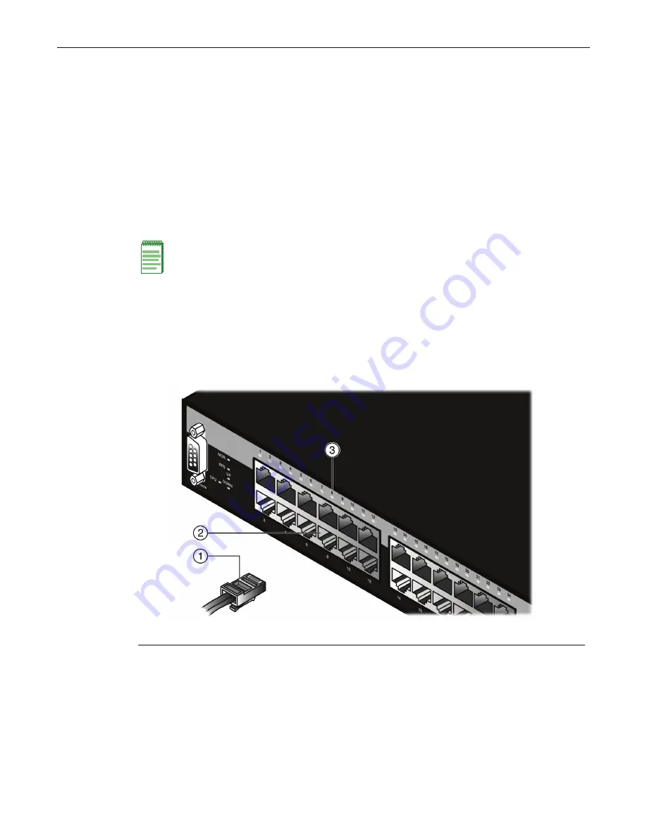
Figure 2-14 Connecting a UTP Cable Segment to RJ45 port
3.
Verify
that
a
link
exists
by
checking
that
the
Link/Activity
LED
is
ON
(solid
green
or
blinking
green).
If
the
Link/Activity
LED
is
OFF,
perform
the
following
steps
until
it
is
on:
a.
Verify
that
the
cabling
being
used
is
Category 5
or
better
with
an
impedance
between
85
and
111 ohms
with
a
maximum
length
of
100
meters
(328
feet).
b. Verify
that
the
device
at
the
other
end
of
the
twisted
pair
segment
is
on
and
properly
connected
to
the
segment.
Note:
All fixed RJ45 front panel ports support Category 5 Unshielded Twisted Pair (UTP)
cabling with an impedance between 85 and 111 ohms. Category 3 cable may be used if
the connection is going to be used only for 10 Mbps.
1
RJ45 connector
2
Port 8
3
Port 8 Link/Activity LED


