background image


The Switch User’s Guide 


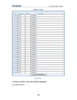
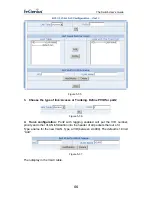
Figure 5-38   

 
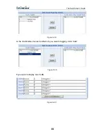
In the VLAN table choose VLAN which you want to tagging. Click “Add” 


Figure 5-39 

 
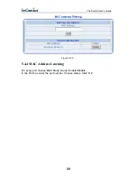
If you want to display one VLAN. 


Figure 5-40   


56 

Содержание ESW-8228

Страница 1: ...24 Port 10 100Mbps 4 built in Combo 10 100 1000Mbps Copper SFP mini GBIC Gigabit Management Switch ESW 8228 User s Guide...

Страница 2: ...ioritization 8 1 4 5 Management features 9 1 5 Panel 9 1 5 1 Front Panel Components 9 1 5 2 Rear Panel 10 1 5 3 LED indicators information 10 1 6 TECHNICAL SPECIFICATIONS 11 2 Installation 12 2 1 Inst...

Страница 3: ...5 2 3 Port Band Restrict 33 5 3 Redundancy 35 5 3 1 Spanning Tree 35 5 3 2 Spanning Tree Confurgration 41 5 3 3 Link Aggregation 42 5 4 Security 43 5 4 1 VLAN 43 5 4 2 MAC Address Bind 57 5 4 3 MAC Ad...

Страница 4: ...ction against harmful interference when the equipment is operated in a commercial environment This equipment generates uses and can radiate radio frequency energy and if not installed and used in acco...

Страница 5: ...rs to other Ethernet switches Notes Notices and Cautions NOTE A NOTE indicates important information that helps you make better use of your device NOTICE A NOTICE indicates either potential damage to...

Страница 6: ...their busses get faster and more users use applications that generate more traffic Upgrading key components such as your backbone and servers to Gigabit Ethernet can greatly improve network response...

Страница 7: ...network loading by dividing a local area network into different LAN segments Dividing a LAN into multiple segments is one of the most common ways of increasing available bandwidth If segmented correc...

Страница 8: ...1000Base LX SX z IEEE 802 3x compliant Flow Control support for full duplex z DB 9 Console port for console managed 1 4 2 Performance Features z 12 8 Gbps switching fabric capacity z Support 8K MAC a...

Страница 9: ...ither 10Mbps or 100Mbps and can operate in half and full duplex transfer modes These ports also support automatic MDI MDI X crossover detection giving true plug and play capability Just need to plug i...

Страница 10: ...raight through serial cable z Radiator Fan This is an equipped for taking from the temperature of the switch NOTICE When the Switch is working Please don t envelop Radiator Fan 1 5 3 LED indicators in...

Страница 11: ...The respective port is connected to The 100Mbps Ethernet network The port is transmitting or receiving data on the 100Mbps Ethernet network The respective port is connected to the 10Mbps Ethernet net...

Страница 12: ...ventilation 2 2 Desktop or Shelf Installation When installing the Switch on the desktop or shelf please attach the rubber feet to the Switch Peel off the protective paper on the pads and attach them o...

Страница 13: ...he Switch conditions and connections 3 2 Hub to Switch A hub 10 or 100BASE TX can be connected to the Switch via a two pair Category 3 4 or 5 UTP STP straight cable For 100Mbps operation a Category 5...

Страница 14: ...ransmission mode for any new twisted pair connection If the attached device does not support auto negotiation or has auto negotiation disabled an auto sensing process is initiated to select the speed...

Страница 15: ...onfigure the Switch to enable its smart functions including Before you configure this device note that when the Switch is configured through an Ethernet connection the manager PC must be set on the sa...

Страница 16: ...ist of the Web Management Utility to settle the device on the Web browser When the following dialog page appears enter the default user name and password and press Login to enter the main configuratio...

Страница 17: ...switch from the console program To start using the Console Management program first connect an EIA 232 serial cable to a COM port on a PC or notebook computer and to the Console Port on the rear panel...

Страница 18: ...The Switch User s Guide Figure 4 3 1 Type in a name for the connection select an icon for the connection and click OK 18...

Страница 19: ...The Switch User s Guide Figure 4 4 2 Select the COM port that you are using for this connection and click OK Figure 4 5 19...

Страница 20: ...th 8 bits Parity none Stop bits 1 Flow Control None 4 You should see some boot up messages displayed within your HyperTerminal session 5 At the username field type in guest or let it be empty and hit...

Страница 21: ...mote management through Telnet over the Ethernet LAN network or even over internet If you are using Microsoft Windows boot up the computer go to Start Run Enter Telnet 192 168 2 11 Click ok Figure 4 7...

Страница 22: ...The Switch User s Guide NOTICE The factory default User name is guest Pass word is guest 22...

Страница 23: ...ss web below Figure 5 1 Enter the appropriate IP Address and Submask and Gateway NOTICE The Switch s factory default IP address is 192 168 2 11 with Submask of 255 255 255 0 and a default gateway of 1...

Страница 24: ...ey management information between agents and NMSs SNMP is the Internet community s de facto standard management protocol SNMP Operations SNMP itself is a simple request response protocol NMSs can send...

Страница 25: ...the person or organization that maintains the switch For example enter Test After complete hereinbefore three steps click ok Figure 5 3 3 Community Configuration Use this table to create an SNMP comm...

Страница 26: ...ion that receives traps the system alerts generated by the switch If no trap manager is defined no traps are issued Create a trap manager by entering the IP address of the station and a community stri...

Страница 27: ...function to change the password Enter old password new password confirm password and click ok Figure 5 8 5 1 4 MAC Address Each Switch must be assigned its own MAC Address You can use this function t...

Страница 28: ...e Web management If turn off this function then all host of the same the network IP address as the Switch IP address can do it Turn on Choose startup Management Host In Management Host IP field input...

Страница 29: ...If don t do it the parameters will lose after reboot system Figure 5 13 5 1 9 Parameters Backup Recovery Backup The backup tools help you to backup the current setting of the Switch Once you need to b...

Страница 30: ...ault setting from the factory Be aware that the entire configuration will be reset the IP address will be retrieved The default IP address of 192 168 2 11 will be used Figure 5 15 CAUTION This operati...

Страница 31: ...tatus Down indicates No Link up indicates Link z Speed Used to set the port speed to either 100Mbps or 10Mbps on Port1 Port24 z 1000Mbps 100Mbps or 10Mbps speed on Port25 and Port26 depending on modul...

Страница 32: ...tch User s Guide Figure 5 17 5 2 2 Port Statistics The Port Statistics page provides a view of the current status of every port on the Switch Pressing the Reset button will reset all port counters to...

Страница 33: ...tch User s Guide Figure 5 18 5 2 3 Port Band Restrict The function provides for the administrator In Band Restrict and Out Band Restrict of every port on the Switch Input the range from 64Kbps to 8000...

Страница 34: ...The Switch User s Guide Figure 5 19 34...

Страница 35: ...unctions z Creates a single spanning tree from any combination of switching or bridging elements z Creates multiple spanning trees from any combination of ports contained within a single switch in use...

Страница 36: ...d directly from a Blocking state to a Forwarding state could create temporary data loops Ports must wait for new network topology information to propagate throughout the network before starting to for...

Страница 37: ...tate is enabled for that port 2 STP Parameters The following are the user configurable STP parameters for the switch level Parameter Description Default Value Bridge Identifier Not user configurable e...

Страница 38: ...t Ethernet ports 4 1000Mbps Gigabit Ethernet ports Default Spanning Tree Configuration Feature Default Value Enable state STP enabled for all ports Port priority 128 Port cost 19 Bridge Priority 32 76...

Страница 39: ...chosen to forward packets 3 Illustration of STP A simple illustration of three switches connected in a loop is depicted in Figure 5 7 In this example you can anticipate some major network problems if...

Страница 40: ...ules In this example only the default STP values are used Figure 5 21 After Applying the STA Rules The switch with the lowest Bridge ID switch C was elected the root bridge and the ports were selected...

Страница 41: ...anning Tree Configuration Configure the following parameters and click the Apply button to implement them Status Default Disabled This field can be toggled between Enabled and Disabled using the pulld...

Страница 42: ...he Link Aggregation Control Protocol LACP provides a standardized means for exchanging information between Partner Systems that require high speed redundant links Port trunks can be used to increase t...

Страница 43: ...runk as a whole z Enable the trunk prior to connecting any cable between the switches to avoid creating a data loop z Disconnect all trunk port cables or disable the trunk ports before removing a port...

Страница 44: ...Generally however it is recommended that the highest priority queue Queue 1 be reserved for data packets with a priority value of 7 Packets that have not been given any priority value are placed in Q...

Страница 45: ...he packet s destination lies on the same segment communications take place using normal Ethernet protocols Even though this is always the case when the destination for a packet lies on another switch...

Страница 46: ...rries the IEEE 802 1Q 802 1p tag The tag is contained in the following two octets and consists of 3 bits of user priority 1 bit of Canonical Format Identifier CFI used for encapsulating Token Ring pac...

Страница 47: ...e PVID within the switch to VID on the network The switch will compare the VID of a packet to be transmitted to the VID of the port that is to transmit the packet If the two VID are different the swit...

Страница 48: ...ally change in conjunction with the change of the port trunk group settings 5 4 1 2 VLAN Configuration z Port based VLANs Packets can only be broadcast among other members of the same VLAN group Note...

Страница 49: ...The Switch User s Guide 49...

Страница 50: ...you want to show or add or modify the VLAN Figure 5 31 z 802 1Q VLAN There are up to 256 configurable VLAN groups By default when 802 1Q is enabled all ports on the switch belong to default VLAN VID 1...

Страница 51: ...of Access and Trunk z Access Ports will strip the 802 1Q tag from all packets that out of those ports If the packet doesn t have an 802 1Q VLAN tag the port will not alter the packet Thus all packets...

Страница 52: ...The Switch User s Guide Figure 5 32 Click OK Next to view the following page Then this page display VALN configuration information of all port 52...

Страница 53: ...The Switch User s Guide Figure 5 33 2 Choose port2 to enter into VLAN configuration The default PVID is 1 53...

Страница 54: ...The Switch User s Guide Figure 5 34 54...

Страница 55: ...rt2 Figure 5 36 4 Trunk configuration Port2 with tagging enabled will put the VID number priority and other VLAN information into the header of all packets that out of it Type a name for the new VLAN...

Страница 56: ...The Switch User s Guide Figure 5 38 In the VLAN table choose VLAN which you want to tagging Click Add Figure 5 39 If you want to display one VLAN Figure 5 40 56...

Страница 57: ...ing to re learn a device s MAC address after it has been disconnected or powered off from the network and then reconnected at some time later If the Network station connected with one port want to con...

Страница 58: ...allows the switch to drop unwanted traffic Traffic is filtered based on the destination addresses In the MAC Address box enter the MAC address that you want to filter out Click Add To Delete a MAC ad...

Страница 59: ...The Switch User s Guide Figure 5 45 5 4 4 MAC Address Learning For every port choose MAC Study status Enable Disable In the Port box enter the port number Choose status Click Ok 59...

Страница 60: ...and destination MAC addresses and their associated port numbers are deleted from the table if they are not accessed within the aging time The aging time can be from 30 to 1 000 seconds with a default...

Страница 61: ...to different types of traffic QoS reduces bandwidth limitations delay loss and jitter It also provides increased reliability for delivery of your data and allows you to prioritize certain applications...

Страница 62: ...fier to determine how the incoming traffic will be classified and thus treated by the Switch 3 Create a QoS profile which associates a service level and a classifier 4 Apply a QoS profile to a port s...

Страница 63: ...8 Figure 5 49 2 VLAN COS QoS settings allow customization of VLAN ID to Traffic classifiers In the field input VID Input you want to mapping COS number To delete an entry from the table simply select...

Страница 64: ...that might be affected by latency problems The IEEE 802 1p Priority specification uses 8 priority levels to classify data packets In 802 1p compliant devices a tag inserted into the packet header is...

Страница 65: ...The Switch User s Guide Figure 5 53 4 Port COS QoS settings allow customization of VLAN ID to Traffic classifiers In the field input the port number Input you want to mapping COS number 65...

Страница 66: ...The Switch User s Guide Figure 5 54 5 COS Queue mapping In the field input COS Input you want to mapping the Queue number 66...

Страница 67: ...The Switch User s Guide Figure 5 55 6 Queue Management The administrator can modify Queue Policy WRR Always High Figure 5 56 If choose WRR this page Show Queue Weight 67...

Страница 68: ...ember of a multicast group on a given subnet work If there are no members on a sub network packets will not be forwarded to that sub network z IGMP Versions 1 and 2 Multicast groups allow members to j...

Страница 69: ...e router assumes that there are no group members on the network The Time to Live TTL field of query messages is set to 1 so that the queries will not be forwarded to other sub networks IGMP version 2...

Страница 70: ...ups of one VLANs In the Port box enter the port number and enter the number of The VLAN VLD Figure 5 61 5 7 Port Analysis 5 7 1 Port Analysis This function is an instrument of diagnosing the network m...

Страница 71: ...or outgoing packet from one port of a network switch to another port where the packet can be studied It enables the manager to keep close track of switch performance and alter it if necessary Configu...

Страница 72: ...8 Storm Restricting The administrator can use this function to limit the amount of Broadcast or Multicast or Flooded for every port Input the range from 64Kbps to 80 000Kbps In the Port box enter the...

Отзывы: