The Switch User’s Guide
1.5.2 Rear Panel
Figure 1-3
Rear Panel view of the Switch
z
AC Power Connector: This is a three-pronged connector that supports the power
cord. Plug
z
In the female connector of the provided power cord into this connector, and the
male into a power outlet. Supported input voltages range from220V AC at 50Hz.
z
Console: This indicator is lit green when the Switch is being managed via
out-of-band/local console management through the RS-232 console port using a
straight-through serial cable.
z
Radiator Fan: This is an equipped for taking from the temperature of the switch.
NOTICE:
When the Switch is working, Please don’t envelop Radiator Fan
1.5.3 LED indicators information
The front panel LEDs provides instant status feedback, and, helps monitor and
troubleshoot when needed.
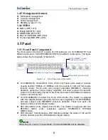
Figure 1-4
Front Panel view of the Switch
z
POWER: Power Indicator
Status
LED
Color
Solid
Blinking Off
PWR Green When the Power LED
lights on, the Switch is
receiving power
N/A
The power cordism
properly
connected.
z
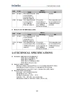
SYS: Management Indicator
Status
LED Color
Solid
Blinking
Off
SYS Green When the CPU is working, N/A
The CPU is not working.
z
Ports 1~24 10/100M Status LEDs
10
Содержание ESW-8228
Страница 22: ...The Switch User s Guide NOTICE The factory default User name is guest Pass word is guest 22...
Страница 34: ...The Switch User s Guide Figure 5 19 34...
Страница 49: ...The Switch User s Guide 49...
Страница 53: ...The Switch User s Guide Figure 5 33 2 Choose port2 to enter into VLAN configuration The default PVID is 1 53...
Страница 54: ...The Switch User s Guide Figure 5 34 54...


