


168
All Enervent ventilation units must be drained. When
air cools down (condenses), condense water forms. For
example in winter time when humid inside air meets cold
heat recovery wheel, or when warm outside air meets the
cooling coil in the ventilation unit (if applicable).
Draining condensate water
•
The condensate water should be led in a falling, at
least Ø15 mm pipe, through a water trap to a floor
drain or such.
•
The pipe must at all times lie lower than the conden-
sate water drip pan / condensate water connection of
the ventilation unit.
•
There must not be any longer horizontal sections on
the pipe.
•
The condensation drain pipe must be insulated if
mounted in spaces where freezing can occur.
•
Only one water lock is allowed for each condensate
water drain.
•
If the unit is equipped with more than one condense
water drains, each one must have a water lock of its
own.
•
There is underpressure in the ventilation unit. We
recommend a height difference of (A) 75 mm, or at
least the underpressure divided with 10 in millimeters
(i.e. 500 Pa under pressure -> 50 mm), between the
unit drain and the water lock drain.
The condense water drain must not be directly
connected to a sewer pipe.
CAUTION
•
We recommend that the height of backwater in the
water lock (B) is 50 mm, or at least the underpressure
divided with 20 in millimeters (i.e. 500 Pa under
pressure -> 25 mm height of backwater). The above
also applies to duct coils for cooling mounted in the
outside air duct or extract air duct.
•
There are over pressure inside duct coils mounted in
the supply air duct. We recommend the height diffe-
rence (A) between the duct coil drain and the water
lock drain is 25 mm. The water lock height of backwa-
ter (B) must be 75 mm, or at least the over pressure
divided with 10 in millimeters (i.e. 500 Pa under
pressure -> 50 mm).
•
The water lock must be filled with water before star-
ting up the unit. The water lock might dry up if water
is not accumulated in it. If this happens, air might
get into the pipe and hinder water from entering the
water lock, which might result in an irritating ”bubb-
ling” sound.
•
The functionality of the water lock must be checked
every year before the heating season and also in the
spring if the ventilation unit is equipped with cooling.
A
B
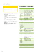
Содержание Pelican eAir
Страница 8: ...8 Kanavaliitännät ulkoilma poistoilma jäteilma tuloilma ...
Страница 20: ...20 13 15 11 14 Lisävaruste 1 2 min 12 9 10 ...
Страница 49: ...49 Ammattilaisen asennusohje ...
Страница 52: ...52 Pelican eAir Installationsanvisningar för ventilationsaggregat Svenska ...
Страница 58: ...58 Kanalanslutningar uteluft frånluft avluft tilluft ...
Страница 70: ...70 13 15 11 14 Extra tillbehör 1 2 min 12 9 10 ...
Страница 99: ...99 Installationsanvisningar för yrkesfolk ...
Страница 102: ...102 Installeringsinstruksjoner for ventilasjonsenheten Norsk Pelican eAir ...
Страница 108: ...108 Kanalanslutningar uteluft avtrekksluft avkastluft tilluft ...
Страница 120: ...120 13 15 11 14 Ekstrautstyr 1 2 min 12 9 10 ...
Страница 149: ...149 Installasjonsinstrukser for fagfolk ...
Страница 152: ...152 Pelican eAir Installation instructions for the ventilation unit English ...
Страница 158: ...158 Duct connections outdoor air extract air exhaust air supply air ...
Страница 170: ...170 13 15 11 14 Extra 1 2 min 12 9 10 ...
Страница 199: ...199 Installation instructions for professionals ...
Страница 205: ...205 ...
Страница 206: ...206 Enervent Zehnder Oy Kipinätie 1 FI 06150 PORVOO Tel 358 207 528 800 enervent enervent com ...
Страница 207: ...207 ...
Страница 211: ...211 Enervent Zehnder Oy Kipinätie 1 FI 06150 PORVOO Tel 358 207 528 800 enervent enervent com ...
Страница 215: ...215 eAir CG periaatekaavio1 eAir CG principschema 1 eAir CG prinsippskisse 1 eAir CG principle schema 1 ...
Страница 216: ...216 eAir CG periaatekaavio 2 eAir CG principschema 2 eAir CG prinsippskisse 2 eAir CG principle schema 2 ...
Страница 217: ...217 eAir CG periaatekaavio 3 eAir CG principschema 3 eAir CG prinsippskisse 3 eAir CG principle schema 3 ...
Страница 218: ...218 eAir CG periaatekaavio 4 eAir CG principschema 4 eAir CG prinsippskisse 4 eAir CG principle schema 4 ...
Страница 219: ...219 eAir CG periaatekaavio 5 eAir CG principschema 5 eAir CG prinsippskisse 5 eAir CG principle schema 5 ...
Страница 220: ...220 eAir CG liitännät eAir CG anslutningar eAir CG koblinger eAir CG connections ...
Страница 223: ...223 ...


