


164
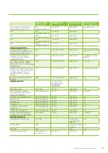
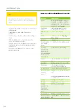
The functions and extras listed in the following table can require external wiring or connecting to work.
Location on MD
controller card
Voltage/current
Cable example
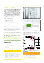
External wiring of
the ventilation unit
AI NTC
Room temperature sensor TE20/
TE21
Connector in the
circuit board of the
eAir control panel
wall mount
3.3 VDC
KLM 2X0.8
Yes
TE01 air temperature outside
X1
3.3 VDC
Quick connector
cable 5 m,
delivered with
the unit
Yes, if pre-heater/
pre-cooler (CHG)
TE10 supply air temperature
X3
3.3 VDC
Quick connector
cable 5 m,
delivered with
the unit
Yes, if duct heating/
cooling coil
TE62 liquid line of a supply air
coil (MDX)
X5
3.3 VDC
Quick connector
cable 5 m,
delivered with
the unit
Yes, if DX duct coil
TE62 (MDX)
TE45 temperature of return
water in heating coil
X12
3.3 VDC
Quick connector
cable 5 m,
delivered with
the unit
Yes, if water heating
coil in the duct
Digital outputs (DO)
Potential-free contact
On/Off control of heating
DO2
Max. 250 VAC / 50 VDC
8 A / 2 A inductive
load
MMJ 3x1.5
Yes, if water heating
On/off control of cooling / On/
off control of heating (MDX)
DO3
Max. 250 VAC / 50 VDC
8 A / 2 A inductive
load
MMJ 3x1.5
Yes, except if HP and
CO
On/Off control of air locks
DO5
Max. 250 VAC / 50 VDC
8 A / 2 A inductive
load
MMJ 3x1.5
Yes
On/Off control of pre-heating /
On/Off control of pre-cooling /
On/Off control of water heating
coil circulating pump (Aqua
KIW)
DO6
Max. 250 VAC / 50 VDC
8 A / 2 A inductive
load
MMJ 3x1.5
Yes, except if Twin
Tropic or in-built
pre-heating coil
Time-controlled relay /
accumulator charge pump
on/off control PU80 (Aqua)
/ exhaust air cooling on/off
control (TCG)
DO7
Max. 250 VAC / 50 VDC
8 A / 2 A inductive
load
MMJ 3x1.5
Yes
A/AB alarm output, closing
DO8
Max. 250 VAC / 50 VDC
8 A / 2 A inductive
load
KLM 2x0.8
Yes
Analog inputs (AI)
%RH1
AI1 (user-defined)
0–10 VDC
KLM 4x0.8
Yes
%RH2 / temperature of water
heater TE80 (Aqua)
AI2 (user-defined)
0–10 VDC
KLM 4x0.8
Yes
Free / PDE10 supply air duct
pressure
AI3 (user-defined)
0–10 VDC
KLM 4x0.8
Yes
Free / PDE30 exhaust air duct
pressure
AI4 (user-defined)
0–10 VDC
KLM 4x0.8
Yes
CO2/1
AI5 (user-defined)
0–10 VDC
KLM 4x0.8
Yes
CO2/2
AI6 (user-defined)
0–10 VDC
KLM 4x0.8
Yes
RH10 supply air relative humidity
sensor (Dehum/Twin Tropic/
TCG)
AI11
(program-defined)
0–10 VDC
KLM 4x0.8
Yes, if duct coil
Содержание Pelican eAir
Страница 8: ...8 Kanavaliitännät ulkoilma poistoilma jäteilma tuloilma ...
Страница 20: ...20 13 15 11 14 Lisävaruste 1 2 min 12 9 10 ...
Страница 49: ...49 Ammattilaisen asennusohje ...
Страница 52: ...52 Pelican eAir Installationsanvisningar för ventilationsaggregat Svenska ...
Страница 58: ...58 Kanalanslutningar uteluft frånluft avluft tilluft ...
Страница 70: ...70 13 15 11 14 Extra tillbehör 1 2 min 12 9 10 ...
Страница 99: ...99 Installationsanvisningar för yrkesfolk ...
Страница 102: ...102 Installeringsinstruksjoner for ventilasjonsenheten Norsk Pelican eAir ...
Страница 108: ...108 Kanalanslutningar uteluft avtrekksluft avkastluft tilluft ...
Страница 120: ...120 13 15 11 14 Ekstrautstyr 1 2 min 12 9 10 ...
Страница 149: ...149 Installasjonsinstrukser for fagfolk ...
Страница 152: ...152 Pelican eAir Installation instructions for the ventilation unit English ...
Страница 158: ...158 Duct connections outdoor air extract air exhaust air supply air ...
Страница 170: ...170 13 15 11 14 Extra 1 2 min 12 9 10 ...
Страница 199: ...199 Installation instructions for professionals ...
Страница 205: ...205 ...
Страница 206: ...206 Enervent Zehnder Oy Kipinätie 1 FI 06150 PORVOO Tel 358 207 528 800 enervent enervent com ...
Страница 207: ...207 ...
Страница 211: ...211 Enervent Zehnder Oy Kipinätie 1 FI 06150 PORVOO Tel 358 207 528 800 enervent enervent com ...
Страница 215: ...215 eAir CG periaatekaavio1 eAir CG principschema 1 eAir CG prinsippskisse 1 eAir CG principle schema 1 ...
Страница 216: ...216 eAir CG periaatekaavio 2 eAir CG principschema 2 eAir CG prinsippskisse 2 eAir CG principle schema 2 ...
Страница 217: ...217 eAir CG periaatekaavio 3 eAir CG principschema 3 eAir CG prinsippskisse 3 eAir CG principle schema 3 ...
Страница 218: ...218 eAir CG periaatekaavio 4 eAir CG principschema 4 eAir CG prinsippskisse 4 eAir CG principle schema 4 ...
Страница 219: ...219 eAir CG periaatekaavio 5 eAir CG principschema 5 eAir CG prinsippskisse 5 eAir CG principle schema 5 ...
Страница 220: ...220 eAir CG liitännät eAir CG anslutningar eAir CG koblinger eAir CG connections ...
Страница 223: ...223 ...