


16
EG-PMS2
PROGRAMMABLE USB SURGE PROTECTOR
All brands and logos are registered trademarks of their respective owners
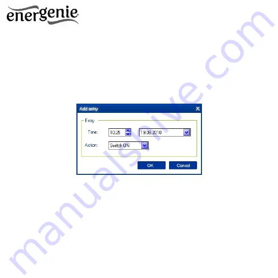
The window
Add entry
will appear (see Figure #7 below). In the
dialog box, specify the required time and the action
Figure #7
To edit the record, select it and click the
Edit
button or just double
click on the entry. The window Edit entry will appear (see Figure #8
below)


