background image

USER and 
MAINTENANCE 
MANUAL

9


UNINTENDED USE

The machine must not be used:


>

in an inflammable and explosive atmosphere different from the self-generated;


>

in extremely dusty environments;


>

by untrained personnel;


>

in non-compliance with the Standards in force;


>

with improper installation;


>

with power supply defects;


>

with total or partial failure to comply with the instructions;


>

with lack of maintenance and/or use of non-original spare parts;


>

with modifications or other interventions not qualifield by the Manufacturer;


>

when the work area is not kept free from tools and other objects;


>

when the work area is not clean enough;


>

in presence of abnormal vibrations in the work area;


>

near heat sources;


>

near to sources of steam;


>

inside of facilities and / or buildings totally or partially closed;


>

in installations with air recirculation�

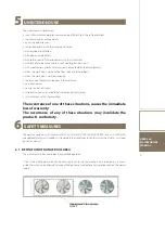
The occurrence of one of these situations, causes the immediate 
loss of warranty.
The occurrence of any of these situations may invalidate the 
product’s conformity.

5


SAFETY MEASURES

The machine complies with Directives 2006/42 EC, 2014/30/UE (EMC), 2014/68/UE (PED) and 2014/34UE (ATEX) 
and applicable Technical Standards as stipulated in the Declaration of Conformity that constitutes an integral 
part of this manual�

6.1  DEFINITION OF DANGEROUS AREA

The machine must be accessed only by qualified operators�

> The internal dangerous area can be accessed by entering the machine� For no reason must access 
inside the machine be allowed to unqualified personnel and before having disconnected the power 
supply�

6

Содержание PURPLE

Страница 1: ...PURPLE PURPLE Natural refrigerant gas R290 USER and MAINTENANCE MANUAL ...

Страница 2: ......

Страница 3: ...8 3 Hydraulic connection to the recovery condenser or sanitary hot water 17 8 4 Instructions for mounting the water flow meter 18 8 5 Water flow rate to the exchangers 19 8 6 Composition of the water 20 8 7 Operation with water to the evaporator at low temperature chiller unit 20 8 8 Operation with water to the condenser at low temperature heat pump unit 21 8 9 Discharge of the safety valves 21 9 ...

Страница 4: ...ry to make regular maintenance activities on the unit as specified in the user manual The unit must always be placed vertically the same rule is valid for transport and installation During the transport the units must be supported by their base module please verify the labels of instructions for the correct lifting points The technical data information and illustrations contained in this manual we...

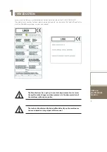
Страница 5: ...age etc are shown on the labels affixed to the machine the following images serve as an example 1 The Manufacturer has a policy for constant improvement and reserves the right to make changes and improvements to the documentation of the machines without prior notice The technical booklet and the labels affixed directly on the machine are to be considered an integral part of this manual ...

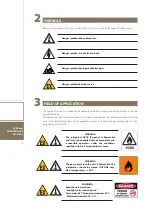
Страница 6: ...eating of air the coils and connecting pipes must be designed for use with R290 3 Danger symbol risk of electric shock Danger symbol moving mechanical parts Danger symbol take extreme care WARNING The refrigerant R290 Propane is flammable and it must be handled only by competent and responsible operators under the conditions specified in the safety regulations in force WARNING The gas content into...

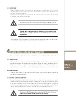
Страница 7: ...ring in mind that it left the factory in perfect condition report any signs of damage immediately to the transporter and make a note of these on the Delivery Sheet before signing it The commercial office or manufacturer should be informed of the extent of the damage as soon as possible The Customer must fill in a written and photographic report concerning any relevant damage 4 2 UNPACKING Disposal...

Страница 8: ...nder or near the load The unit must be transported by qualified personnel forklift operator slinging personnel who must wear the necessary personal protective equipment overalls safety shoes work gloves hard hats goggles The Manufacturer declines all responsibility for any accident caused by non compliance with this warning Keep the forks low Use ballasts in the event of unbalancing Do not hold pr...

Страница 9: ...work area near heat sources near to sources of steam inside of facilities and or buildings totally or partially closed in installations with air recirculation The occurrence of one of these situations causes the immediate loss of warranty The occurrence of any of these situations may invalidate the product s conformity 5 SAFETY MEASURES The machine complies with Directives 2006 42 EC 2014 30 UE EM...

Страница 10: ... operate in the drain path of the safety valves If the units are positioned in places that are not protected and can be easily reached by unqualified persons it is mandatory to install suitable protections The user is obliged to consult the installation and use manuals of the systems incorporated and atta ched to this manual There may be potential risks that are not evident Warning and signs are t...

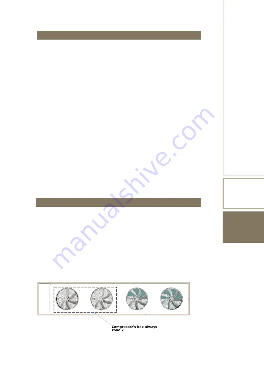
Страница 11: ...SONNEL QUALIFICATIONS OBLIGATIONS The user must know and apply the prescriptions regarding occupational safety in compliance with Directives 2006 42 EC and 1999 92 EC Maintenance of electrical apparatus installed in compressor s box shall be berformed according to EN 60079 14 and EN 60079 17 maintenance operators should be qualified according to EN 60079 14 The knowledge and comprehension of the m...

Страница 12: ...nit The unit must always be anchored to the ground Provide a solid base on which to position the unit This support must be perfectly flat and horizontal Its dimensions must be suitable for those of the unit This precaution is indispensable when the unit is to be positioned on unstable ground various lands gardens etc Although the unit transmits low levels of vibrations to the supporting structure ...

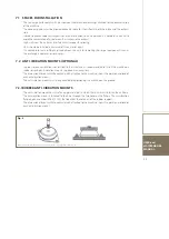
Страница 13: ...PTIONAL In order to reduce vibrations transmitted to the structure it is recommended to install the machine on rubber or spring anti vibration mounts supplied as an accessory The dimensional layout with the contact patch attached to the machine shows the position and load of each antivibration mount The anti vibration mounts must be applied before positioning the machine on the ground 7 2 1RUBBER ...

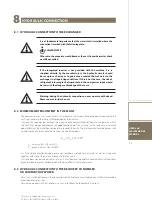
Страница 14: ...r maintenance of the system pressure and to compen sate heat dilation drain valve and where necessary drain tank to empty the system for maintenance operations or sea sonal breaks It is mandatory to comply with these prescriptions to facilitate the hydraulic connection operations maintenance and access to the electrical panel Itishighlyrecommendedtoinstallasafetyvalveonthehydrauliccircuit If serio...

Страница 15: ...FL Flow meter RB Cock 06 Tank 07 Manometer 08 Thermometer 09 Water filter 10 Bleed valve 11 Flexible coupling 12 Plant filling unit 13 Water outlet 14 Flow meter 15 Plates exchanger PA Well for anti freeze probe PF Well for water inlet probe 03 Safety valve RE Tank electrical heater Storage tank capacity 10 Bleed valve 02 Expansion tank Use two keys to tighten the hydraulic connections see fig 3 U...

Страница 16: ...el 1 dBA 69 70 70 71 71 79 79 79 79 81 81 Noise pressure level 10 m 2 dBA 41 42 42 43 43 51 51 51 51 53 53 Unit size 50 1 55 1 60 1 75 1 35 2 40 2 45 2 50 2 55 2 60 2 75 2 80 2 Acoustic data LN version Sound power level 1 dBA 84 84 86 86 86 88 88 88 88 90 90 90 Noise pressure level 10 m 2 dBA 56 56 58 58 58 60 60 60 60 62 62 62 Acoustic data SLN version 3 Sound power level 1 dBA 81 81 83 83 83 85 ...

Страница 17: ...rovided by the machine It is necessary to guarantee inertia on the system such to limit oscillation of the water temperature within the limits that do not compromise the good functioning of the unit and at the same time guarantee good stability at the water flow temperature towards the utility The mathematical formula below is for calculating the minimum water content on the side of the plant Vmin...

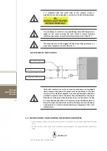
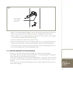
Страница 18: ... s safety devices 3 way valve Recovery water output Recovery water input 8 4 INSTRUCTIONS FOR MOUNTING THE WATER FLOW METER Clean the pipes making sure that any metal residue cannot interfere with correct operation of the flow meter Connect the flow meter to the male threaded outlet coupling on the evaporator fig 4 bearing this label Seal the connection with Teflon tape WATER OUT It is important t...

Страница 19: ...ectric control board as indicated in the electrical diagram To disassemble the flow meter unscrew the plastic locking ring When reassembling the flow meter put the ring seal between the metal fitting and the plastic part 8 5 WATER FLOW RATE TO THE EXCHANGERS The nominal water flow rate refers to a thermal gradient of 5 C between the inlet and outlet The maximum water flow rate refers to a thermal ...

Страница 20: ...c substances in the water that could pass through the filter and settle in the heat exchangers which would lead to malfunction and or damage in time If the water used in the unit contains organic substances the warranty is immediately rendered null and void 8 7 OPERATION WITH WATER TO THE EVAPORATOR AT LOW TEMPERATURE CHILLER UNIT With temperatures below 5 C it is good practice to operate with wat...

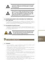
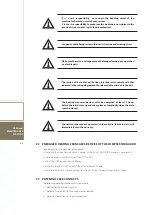
Страница 21: ...electric motors ELECTRIC CONNECTIONS 9 1 OVERVIEW The electrical connections must comply with the information shown on the wiring diagram attached to the unit and the regulations in force in the place of installation The earth connection is mandatory by law The installer must connect the earth cable using the rele vant PE clamp on the earth bar situated in the electric control board Verify that th...

Страница 22: ...re the initial start up and takes place automatically when the main switch is closed The unit must be made to operate with those limits failure to do so will immediately void the warranty 9 2 ENERGIZED HEATING CRANCASES DEVICES OF THE COMPRESSOR GUARD To energized heating crancases of the guard Make sure that the phase sequence is correct if the PHASE MONITOR accessory is not present Close the mai...

Страница 23: ... This control is calibrated and inspected in the factory If the external pump is controlled by an external controller the pump must be started before the unit and stopped after it the latter shuts down with a recommended minimum advance delay of 5 minutes Warning the speed control calibrations must never be modified If this is required please contact the manufacturer 9 4 CIRCULATION PUMP ELECTRIC ...

Страница 24: ...witch is closed To check the correct functioning of the resistances check that the lower part of the compressors is hot and in all cases is at a temperature of 10 15 C over the environment temperature Check that the hydraulic connections have been made correctly respecting the indications on the input output plates on the machine Check that the hydraulic system has been bled thereby eliminating al...

Страница 25: ...safety devices should be checked The calibration settings are shown in Table 2 11 The control equipment should be serviced by qualified staff only Incorrect calibration settings can cause serious damage to the unit and injuries to people Control and safety components Activation set point Differential Reset Safety valve setting 30 0 bar High pressure switch setting 27 5 bar 4 Controller manual Low ...

Страница 26: ...button This turns off the power to the entire machine 12 Iftheunitdoesnotstartup nevermodifytheinternalelectricalconnections otherwise the warranty is immediately rendered null and void It is recommended not to disconnect the power supply from the unit during short stop periods in order to leave the compressors heating crancase resistances powered do so only in the case of prolonged stops e g seas...

Страница 27: ...utes after the power supply has been disconnected at the main switch Before carrying out any maintenance turn off the machine at the main switch wait at least 5 minutes always use a suitable multimeter to make sure that there is no dangerous voltage at the heads of the clamps always make sure that the motor of the compressor has completely stopped Freely rotating motors can create dangerous voltag...

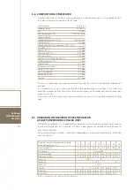
Страница 28: ...point of the fluid used throughout the standstill period Seasonal Verify the filling of the water circuit Monthly Verify the operation of the flow meter Monthly Check the heater of the compressor guard Monthly Clean the metal filters in the hydraulic pipes Monthly Clean the finned battery and the metal filters if present using compressed air in the opposite direction to the passage of air If it is...

Страница 29: ...ervice valve and connect the lubricant hand pump discharge 8 connect the hand pump suction to the lubricant package 9 by acting the hand pump introduce the right oil quantity in the compressor crankcase 10 remove the hand pump from the service valve 11 connect the vacuum pump suction line to the Schrader service valve 12 start the vacuum pump and evacuate the compressor for at least 15 minutes 13 ...

Страница 30: ... s structure and components if no longer usable should be taken down and divided by type of material this regards in particular copper and aluminium parts of which there are fair amounts in the unit This is to ease collection disposal and recycling centres and minimise environmental impact 14 The refrigerant gas it contains must be recovered by specialised staff and sent to collection centres Part...

Страница 31: ... 2008 CLP Hazard pictogram s GHS02 GHS04 Hazard pictograms code GHS02 GHS04 Signal word Danger Hazard statements H220 Extremely flammable gas H280 Contains gas under pressure may explode if heated Precautionary statements Prevention Response Storage P210 Keep away from heat sparks open flames hot surfaces No smoking P377 Leaking gas fire Do not extinguish unless leak can be stopped safely P381 Eli...

Страница 32: ...tion 11 4 FIRST AID MEASURES 4 1 Inhalation Remove patient from exposure keep warm and at rest Administer oxygen if necessary Apply artificial respiration if breathing has ceased or shows signs of failing In the event of cardiac arrest apply external cardiac massage Obtain immediate medical attention Skin contact Thaw affected areas with water Remove con taminated clothing Caution clothing may adh...

Страница 33: ...eathing apparatus when entering area unless atmosphere is proved to be safe Evacuate area Ensure adequate air ventilation Eliminate ignition sources 6 2 Environmental precautions Try to stop release Prevent from entering sewers basements and work pits or any place where its accumulation can be dangerous 6 3 Clean up measures Ventilate area 7 HANDLING AND STORAGE 7 1 Handling Take precautionary mea...

Страница 34: ...weetish Poor warning properties at low concentrations 9 5 Molecular weight 44 9 6 Solubility in water mg l 75 Boiling point oC 42 1 9 7 Melting point C 188 0 9 8 Relative density gas air 1 1 5 9 9 Relative density liquid water 1 0 58 9 10 Vapour pressure 20 C 8 3 bar 9 11 Flammability range vol in air 1 7 to 9 5 9 12 Auto ignition temperature C 470 9 13 Other data Gas vapour heavier than air May a...

Страница 35: ...f category B C D and E Other carriage Passage forbidden through tunnels of category D and E Sea transport IMO IMDG code Proper shipping name Propane Class 2 1 IMO Packing group P200 Emergency schedule EmS Fire F D Emergency schedule EmS Spillage S U Instructions Packing P200 Air transport ICAO IATA Proper shipping name Propane Class 2 1 Passenger and cargo aircraft Cargo aircraft only Packing inst...

Страница 36: ...believed to be accurate and is given in good faith but it is for the user to satisfy itself of the suitability for its own particular purpose Accordingly Harp International Limited gives no warranty as to the fitness of the product for any particular purpose and any implied warranty or condition statutory or otherwise is excluded except to the extent that such exclusion is prevented by law 15 2 IM...

Страница 37: ...USER and MAINTENANCE MANUAL 37 ...

Страница 38: ......

Страница 39: ......

Страница 40: ...de legale Via dell Industria 24 35028 PIOVE di SACCO Padova Italy Sede operativa Via G Puccini 9 30010 CANTARANA di CONA Venezia Italy Tel 39 0426 302051 Fax 39 0426 840000 www enerblue it info enerblue it DT00108Rev02 ...

Отзывы: