BA00300K/09/en/13.1071120094
Software version:01.00.xx
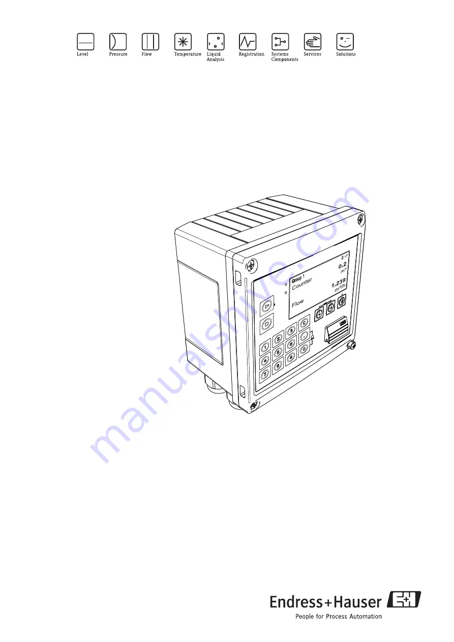
Operating Instructions
RA33
Batch controller
Страница 1: ...BA00300K 09 en 13 10 71120094 Software version 01 00 xx Operating Instructions RA33 Batch controller ...
Страница 2: ...rief overview For quick and easy commissioning Safety instructions ä 4 Installation ä 8 Wiring ä 15 Display and operating elements ä 21 Commissioning ä 25 Applications for the batch controller a0014548 en Fig 1 Brief overview of applications ...
Страница 3: ...ensors 17 4 4 Outputs 18 4 5 Communication 19 4 6 Post connection check 20 5 Operation 21 5 1 General notes for operation 21 5 2 Display and operating elements 21 5 3 Operating matrix 24 6 Commissioning 25 6 1 Quick commissioning make it run 25 6 2 Applications 25 6 3 Configuring the basic parameters general device functions 32 6 4 Optional device settings special functions 43 7 Maintenance 44 8 A...
Страница 4: ...nnel authorized to perform such work and instructed by the facility s owner operator The skilled personnel must have read and understood these Operating Instructions and it is mandatory for them to follow the instructions they contain The operator must ensure that the measuring system is cor rectly wired in accordance with the wiring diagrams When the housing cover is removed the shock protection ...
Страница 5: ...or procedures that can lead to defective operation or to destruction of the device if not carried out properly Warning This symbol draws attention to activities or procedures that can lead to injuries to persons to a safety risk or to destruction of the device if not carried out properly Note This symbol draws attention to activities or procedures that have an indirect effect on operation or can t...
Страница 6: ... revision 9 Degree of protection 10 Place and year of manufacture 2 2 Scope of delivery The scope of delivery of the batch controller comprises Batch controller field housing Brief Operating Instructions in paper form Operating Instructions and additional documentation on CD ROM Optional interface cable and DVD set with FieldCare Device Setup parameter configuration soft ware Optional Field Data M...
Страница 7: ... factory in perfect condition as regards technical safety The device meets the relevant standards and direc tives as per EN 61 010 Safety requirements for electrical equipment for measurement control and laboratory use Thus the device described in these Operating Instructions meets the legal requirements of the EU Directives The manufacturer confirms successful testing of the device by affixing to...
Страница 8: ...the packaging or contents damaged Are the delivered goods complete Compare the scope of delivery with your order information 3 1 2 Transport and storage Observe the following points Pack the device in such a way as to protect it reliably against impact for storage and transporta tion The original packaging provides optimum protection The permitted storage temperature range is 40 to 85 C 40 to 185 ...
Страница 9: ...ount pipe mounting panel mounting and top hat rail installation The orientation is only determined by the legibility of the display Connections and outputs are fed out of the bottom of the device The pipes are connected via coded clamps Operating temperature range 20 to 60 C 4 to 140 F Caution To prevent heat build up do not expose the device to extreme heat or strong direct sunshine Operating the...
Страница 10: ...troller to the mounting plate and fasten it in place from the rear using 4 screws 3 Fasten the mounting plate to the wall using 4 screws a0014170 Fig 7 Wall mounting 3 4 2 Panel mounting 1 Make the panel cutout in the required size dimensions å 5 2 Attach the seal item 1 to the housing a0014283 Fig 8 Panel mounting 3 Screw the threaded rods item 2 into the mounting plate dimensions å 4 ...
Страница 11: ... the mounting plate for panel mounting 4 Push the device into the panel cutout from the front and attach the mounting plate to the device from the rear using the 4 screws provided item 3 5 Fasten the device in place by tightening the threaded rods a0014284 Fig 10 Panel mounting ...
Страница 12: ...en the top hat rail adapter item 1 dimensions å 6 to the device using the screws provided item 2 and open the top hat rail clips a0014176 Fig 11 Preparing for top hat rail mounting 2 Attach the device to the top hat rail from the front and close the top hat rail clips a0014177 Fig 12 Top hat rail mounting ...
Страница 13: ...ounting 1 Pull the steel belts through the mounting plate dimensions å 4 and fasten them to the pipe a0014178 Fig 13 Preparing for pipe mounting 2 Attach the device to the mounting plate and fasten it in place using the 4 screws provided a0014179 Fig 14 Pipe mounting ...
Страница 14: ...ch Controller RA33 14 Endress Hauser 3 5 Post installation check Note For installing the batch controller and the associated temperature sensors observe the general installation instructions according to EN 1434 Part 6 ...
Страница 15: ...r cable 4 2 Quick wiring guide a0014120 Fig 15 Connection diagram of the batch controller For the connection of the communication interfaces see the Communication section ä 19 Terminal assignment Terminals Terminal assignment Inputs 1 RTD power supply Temperature Optionally RTD or current input 2 RTD power supply 5 RTD sensor 6 RTD sensor 52 0 4 to 20 mA input 53 Ground for 0 4 to 20 mA input 54 0...
Страница 16: ...l for end of batch fault 61 status pulse output 1 open collector 62 status pulse output 2 open collector 63 status pulse output 2 open collector 70 0 4 to 20mA pulse output Current values e g power or counter values e g energy 71 0 4 to 20mA pulse output 13 Relay 1 normally open NO Batch control pump valve fault 14 Relay 1 normally open NO 23 Relay 2 normally open NO 24 Relay 2 normally open NO 90...
Страница 17: ...ing EN 1434 Type IB IC ID IE 2 Current pulses 3 0 4 to 20 mA signal not in combination with MID approval option Flow sensors with power supply via the batch controller a0014180 Fig 18 Connecting active flow sensors 1 4 wire sensor 2 2 wire sensor 4 3 2 Temperature Connecting the RTD sensors a0014185 1 4 wire connection 2 3 wire connection 3 2 wire connection Terminals 1 2 5 6 T warm Terminals 3 4 ...
Страница 18: ...Pulse output Active voltage pulses are output at the pulse output Voltage level 0 to 2 V corresponds to Low level 15 to 20 V corresponds to High level Maximum output current 22 mA 4 4 3 Open collector output The two digital outputs can be used as status or pulse outputs Make the selection in the following menus Setup É Advanced setup or Expert É Outputs É Open Collector Temperature transmitter con...
Страница 19: ...gland is available for this pur pose which allows users to guide pre terminated cables through the housing Via the Ethernet inter face the device can be connected using a hub or a switch or directly to office equipment Standard 10 100 Base T TX IEEE 802 3 Socket RJ 45 Max line length 100 m a0014600 Fig 19 Ethernet TCP IP Modbus TCP connection 1 Ethernet RJ45 2 Cable entry for Ethernet cable 4 5 2 ...
Страница 20: ... testing voltage 500 V and is used to connect a printer It is connected via a 3 pin plug in terminal in the housing cover a0014602 Fig 21 Printer connection via RS232 4 6 Post connection check After completing the device s electrical installation carry out the following checks Device status and specifications Notes Is the device or cable damaged visual inspection Electrical connection Notes Does t...
Страница 21: ...g 22 Display and operating elements of the batch controller 1 LED green Operation 2 LED red Fault indicator Function keys 3 Start 4 Stop 5 Numerical keypad 6 Start printing Interface 7 USB connection for configuration Operating keys 8 E Display 9160 x80 DOT matrix display Note Green LED for voltage red LED for alarm error Green LED is always illuminated as soon as power is supplied to the device S...
Страница 22: ...in the Dis play menu or by pressing one of the keys 0 9 or period It does not matter whether a batching pro cess is currently active when you enter the value The new preset counter value is used when the next batching process is started Note If the preset counter is part of a display group the preset counter value which is valid for the current batch is always displayed If the value is changed whe...
Страница 23: ...erate project via File New 4 Select communication DTM CDI Communication USB 5 Add EngyCal RH33 or RS33 6 Click Establish connection 7 Start online configuration Carry out the rest of the configuration of the device according to these Operating Instructions for the device The entire Setup menu i e all parameters listed in these Operating Instructions is also included in the FieldCare Device Setup N...
Страница 24: ... figuring the instrument function Units Signal type Pulse value value for pulse signal type or Start of measuring range for current sig nal type End of measuring range for current sig nal type Unit Counter unit Date and time Parameters for quick commissioning Advanced setup settings that are not essential for basic operation of the device Special settings can be configured via Expert Diagnostics m...
Страница 25: ...I US É Signal type Select the signal type for flow pulse or current É Unit Select the flow unit É Counter unit Specify the unit for the volume counter É Pulse value value Enter the unit and value for the pulse value of the flow transmitter for pulse signal type É Meas range start and Meas range end for current signal type É Date time Set the date and time The device is now operational and ready to...
Страница 26: ...nes the quantity of medium which the Batch Controller RA33 batches as precisely as possible The last preset counter value to be used is stored in the device and applied for new batching operations until the value is changed d After run correction The first time the automatic after run correction function of the Batch Controller RA33 is used the controller first has to learn what the after run quan...
Страница 27: ... collector Required settings a Flow input Enter pulse value or measuring range of the 0 4 to 20 mA input b Valve control Set the choice of filling stages to 2 stage Assign the selected outputs to control the filling stages Display variables Preset counter volume batch counter volume volume flow daily monthly and annual counters and totalizer for batched quantity number of batches Miscellaneous not...
Страница 28: ...nd temperature range or enter temperature measur ing range for the 4 20 mA input c Select the product group of the mineral oil d Select the type of density measurement Since the density is not measured the Operating den sity parameter has to be set to Calculated e Select the reference density The reference conditions of the corrected volume must be assigned for the reference density Here the volum...
Страница 29: ...ty current input Output signals Valve control relay or open collector Pump control analog output relay or open collector Required settings a Flow input Enter pulse value or measuring range of the 0 4 to 20 mA input b Temperature input Select the RTD type and temperature range or enter temperature measur ing range for the 4 20 mA input c Select the product group of the mineral oil d Select the type...
Страница 30: ...trol relay or open collector Pump control analog output relay or open collector Required settings a Flow input Enter pulse value or measuring range of the 0 4 to 20 mA input b Set the product group to User defined c Select the type of density measurement The Operating density is set to Measured since a density meter is used in this application example d Set the The result is parameter to Mass to e...
Страница 31: ... Input signals Flow pulse input or current input Remote control digital input Output signals Valve control relay or open collector Required settings a Flow input Enter pulse value or measuring range of the 0 4 to 20 mA input b Set the batch controller to Manual mode c The digital inputs must be assigned a Start stop function for remote control d Valve control Set the choice of filling stages to 1 ...
Страница 32: ... values The current flow can also be calculated from the counters so that it can be shown on the display The required flow unit must first be selected in the flow settings Floating contacts reed transmitters Flow current signal For flow transmitters with current signal output the flow measuring range is scaled in Advanced setup ä 61 Adjustment calibration of the current input To adjust the current...
Страница 33: ...upÉAdvanced setupÉInputsÉTemperature Refer also to Compensation ä 43 Density optional To measure the density a density sensor can be connected to the current input marked Density via 0 4 to 20 mA Refer also to Compensation ä 43 Digital inputs Two digital inputs are available Depending on the options of the device the following functions can be controlled via the digital inputs Function Description...
Страница 34: ...flow or the volume mass counter Furthermore the progress of the batch can be output in linear or curve form Batch progress When the progress of the batch is displayed the output value starts at 20 mA at the beginning of the batch and moves down linearly until it reaches the lower limit of the current output 0 4 mA at the end of the batch The output s lower range limit is issued at the current outp...
Страница 35: ...y time so that the required batching quantity is achieved faster This stage is closed when a remaining pre stop quantity is reached The delay time and pre stop quantity must also be specified in the batch settings Function Description Standard Standard mode A value must be entered for the preset counter after commissioning This value is then used for all batch cycles until it is changed The value ...
Страница 36: ...ber can also be preset as well as the current number reset to this value Display groups Display settings Under Application Grouping in the Setup menu select which process values are shown in the dis play For this purpose 6 display groups are available A group can be assigned up to 3 values For a three line display the values are displayed in a smaller font size A user defined name can be assigned ...
Страница 37: ...ll stored values can be read out using the Field Data Manager Software only Specifically the following data are stored in the device General notes for data logging The time of data logging start time of the logging intervals can be configured and or synchronized via the time of day The current evaluations min max average counter can be reset to zero individually or com pletely via setup The archiv...
Страница 38: ...ace only Process values such as flow cannot be transmitted to the device via the bus interfaces Batch commands can be sent to the device via Modbus for details refer to Modbus RTU Depending on the bus system alarms or faults are displayed as part of data transmission e g status byte The process values are transmitted in the units that are also used for display on the device Only the counter readin...
Страница 39: ...0 Status of first measured value 16 bit integer high byte first Register 001 to 002 First measured value 32 bit float high byte first 16 6 5 4 3 2 1 not used 0 0 0 0 ok 0 0 0 1 Open circuit 0 0 1 0 Over range 0 0 1 1 Under range 0 1 0 0 Invalid measured value 0 1 1 0 Replacement value 0 1 1 1 Sensor error 1 Lower limit value violated 1 Upper limit value violated 1 Counter overflow ga Slave address...
Страница 40: ...communication to PC software Field Data Manager Software FieldCare OPC server Web server Modbus TCP ä 38 Up to 4 connections can be opened simultaneously e g Field Data Manager software Modbus TCP and 2x Web server However only one data connection via Port 8000 is possible As soon as the max number of connections is reached new connection attempts are blocked until an existing connection is termin...
Страница 41: ...ce is indicated in minutes in the subsequent entry Version 1 The XML file is available in ISO 8859 1 Latin 1 encoding at the address http IP address index xml alternatively http IP address xml However this encoding cannot display some special characters such as the sum sign Strings such as digital status information are not transmitted Version 2 A UTF 8 encoded XML file can be retrieved at the add...
Страница 42: ...ber of printouts are additionally printed after every batch cycle Baudrate Select the baudrate that is compatible with the printer Number of copies Use this option to specify the number of printouts for automatic printing at the end of the batch Characters line Use this option to enter the number of characters per line supported by the printer Number of headers Use this option to select the requir...
Страница 43: ...at which the correction must be calcu lated The options available for selection are 15 C 20 C or 60 F The value that must be entered in the reference density parameter is the density of the medium under the selected reference operating conditions An expansion coefficient must be specified depending on the calculation and if density measure ment does not take place It must be entered in the unit 1 ...
Страница 44: ...enance work is required for the device 8 Accessories When ordering accessories please specify the serial number of the device USB cable and FieldCare Device Setup calibration software incl DTM library RXU10 G1 Visualization software with Field Data Manager SQL based database software ...
Страница 45: ...rrently pending or if one of them has occurred multiple times 2 Open measured value display diagnostics Verify the input signals by displaying the raw values mA Hz Ohm or the scaled measuring ranges To verify calculations call up calculated aux iliary variables if necessary Snapshot of raw value display 3 Steps 1 and 2 remedy most causes of errors If the error persists observe the troubleshooting ...
Страница 46: ...ontact service M302 Setup has been loaded from backup No effect on operation To be safe check setup configuration and adjust if necessary F303 Device data defective Contact service M304 Device data defective The system continues working with backup data No action required F305 Counters defective Counter value is reset automatically to 0 M306 Counter defective but system could continue working with...
Страница 47: ...mory i e if the memory is full the oldest messages are overwritten automatically without message The following information is stored Date time Error number Fault Text The diagnosis list is not read out via PC operating software However it can be displayed via Field Care The following fall under Fxxx or Mxxx Open circuit Sensor error F501 Invalid configuration Check setup M502 Device is locked e g ...
Страница 48: ...relay manually Analog output Allows you to output a current value for test purposes You can configure fixed values 3 6 mA 4 0 mA 8 0 mA 12 0 mA 16 0 mA 20 0 mA 20 5 mA 21 0 mA Pulse outputs Pulse OC Allows you to output pulse packages for test purposes The following frequencies are possible 0 1 Hz 1 Hz 5 Hz 10 Hz 50 Hz 100 Hz 200 Hz 500 Hz The following simulations are possible for the pulse outpu...
Страница 49: ...2 Housing base lasered incl threaded plate specify serial number XPR0001 UT 3 Cover electronic internal for RA33 incl screws for Mainboard CPU card XPR0001 CB 4 Set of small parts Hinge pins pressure compensation element USB cover panel seal XPR0001 SP 5 Cable insertion set for panel mounting 4xM20 2xM12 1xM25 XPR0001 SK 6 Mainboard XPR0003 Approval AA Non hazardous area CP CSA General Purpose Sup...
Страница 50: ... 0 71084277 W O Item No Pipe mounting set XPR0001 RM Wall mounting set XPR0001 WM DIN rail mounting set XPR0001 DM Panel mounting set incl panel seal XPR0001 SM Plug in terminal 3 pin FMC1 5 3 ST 3 5 for digital I O and RS485 51009210 Field Data Manager Software MS20 Visualization software and database for displaying stored measur ing calibration and configuration data Manipula tion protected SQL ...
Страница 51: ... best protection Repairs must only be carried out by your supplier s service orga nization Note When sending for repair please enclose a note with a description of the error and the application 9 7 Disposal The device contains electronic components and must therefore be disposed of as electronic waste in the event of disposal Please also observe local regulations governing disposal ...
Страница 52: ...ital output 250 RTD Current relay digital output 440 Cable open circuit detection Current relay digital output 440 Cable open circuit detection RTD Current relay digital output 1100 Pulse input Pulse output 440 Pulse input Relay digital output 250 Measuring range 0 4 to 20 mA 10 over range Accuracy 0 1 of full scale value Temperature drift 0 01 K 0 0056 F of the full scale value Loading capacity M...
Страница 53: ...pedance load 50 Ω Accuracy during frequency measurement Basic accuracy 0 01 of measured value Temperature drift 0 01 of measured value over entire temperature range Measuring range 0 4 to 20 mA 10 over range Accuracy 0 1 of full scale value Temperature drift 0 01 K of full scale value Loading capacity Max 50 mA max 2 5 V Input impedance load 50 Ω A D converter resolution 24 bit HART signals are no...
Страница 54: ...tching cycles since in contrast to relays these outputs are non wearing Auxiliary voltage output transmitter power supply The auxiliary voltage output can be used to power the transmitter or control the digital inputs The auxiliary voltage is short circuit proof and galvanically isolated 500 V testing voltage towards all other inputs and outputs Output range 0 4 to 20 mA 10 over range Load 0 to 60...
Страница 55: ...al and cannot be combined with other optional interfaces It is galvanically isolated testing voltage 500 V A standard patch cable e g CAT5E can be used to connect the Ethernet interface A special cable gland is available for this purpose which allows users to guide pre terminated cables through the housing Via the Ethernet interface the device can be connected to office equipment using a hub or a ...
Страница 56: ...times is reliably measured by the Batch Controller but can deviate by this amount from the preset fill quantity Using the after run correction function or reducing the flow for 1 stage batching increases the accuracy of the quantity transferred The use of two batching stages allows for batching that is both fast and precise 10 0 6 Installation Installation instructions Mounting location Wall pipe ...
Страница 57: ... g 1 5 lbs Material Housing fiber glass reinforced plastic PBT GF30 Terminals Spring terminals 2 5 mm2 14 AWG auxiliary voltage with plug in screw terminal 10 0 9 Human interface Display elements Display 160 x 80 dot matrix LCD with white background color switches to red in an alarm condition active display area 70 x 34 mm LED status display Operation 1 x green Fault indication 1 x red ...
Страница 58: ...the display to their original values Print function Press 0 and simultaneously to print out the last batch run The RS232 printer interface feature must be purchased to be able to use this function Configuration interface USB interface front panel optional Ethernet interface configuration via PC with PC operating software FieldCare Device Setup Data logging Real time clock Drift 15 min per year Pow...
Страница 59: ...and laboratory use IEC 61326 series Electromagnetic compatibility EMC requirements NAMUR NE21 NE43 Association for Standards for Control and Regulation in the Chemical Industry ASTM D1250 04 API MPMS 11 1 Manual of Petroleum Measurement Standards Chapter 11 Physical Properties Data Section 1 Other approvals CSA GP UL listed ...
Страница 60: ...tivated in Setup Advanced setup Application Batch information Preset counter 020100 Please enter preset counter Change group Choose the group which should be displayed Change automatically between the configured display groups or display one of the 6 display groups ä 36 Display brightness You can adjust the brightness of the display here Number 1 99 Contrast display You can adjust the contrast of ...
Страница 61: ...s Enter the beginning of the measuring range here Example 0 100 m3 h of the sensor is transformed 4 20 mA 0 Meas range end 210009 00 Enter the end of the measuring range here e g 100 for a transmitter with 0 100 m3 h Date time Show and set date and time UTC time zone 120000 00 Current UTC time zone on UTC coordinated universal time Actual date 120001 00 Actual date Format as configured under date ...
Страница 62: ...on 110003 00 Selects the regional settings for summer normal time changeover Begin summer time Occurrence 110005 00 Day in spring on which the switch from standard time to summer time takes place e g for the fourth Sunday in March select 4 Day 110006 00 Day of the week on which the switch from standard time to summer time takes place in spring e g for the fourth Sunday in March select Sunday Month...
Страница 63: ...net interface only Modbus Configure the Modbus settings for the device Note For devices with Modbus optional only Device address 480000 00 Enter the device address where it should be possible to reach this device in the bus Baudrate 480001 00 Set the transmission rate for communication Parity 480002 00 Please check that settings are compatible with the PC set tings Port 480004 00 Port via which th...
Страница 64: ...n RTD 990009 00 Inputs Settings for the analog and digital inputs Flow Settings for the flow input Signal type 210000 00 Select the signal type connected 4 to 20 mA DP Flow Input for flow measurements based on the differential pressure method e g orifice plate Pulse U IB IC Input for active voltage pulses and contact sensors as per EN 1434 2 Class IB IC Pulse Cl ID IE Pulse input for contact senso...
Страница 65: ... y all values around the zero point i e including negative values are not recorded Decimal number max 8 digits including decimal separa tor Temperature Settings for the temperature input Signal type 220000 00 Select the signal type connected Connection 220001 00 Configure whether RTD is to be connected with 3 or 4 wires Only for signal type Pt100 Pt500 or Pt1000 Channel ident 220002 00 Name of the...
Страница 66: ...Select which channel or calculated value is to be output at the output Start Value 310003 00 Configure what value corresponds to 0 4 mA Numerical value max 8 digits including decimal separa tor Full scale value 310004 00 Configure what value corresponds to 20 mA Numerical value max 8 digits including decimal separa tor Damping 310005 00 Time constant of the first order low pass for the output sig ...
Страница 67: ...al value max 8 digits including decimal separa tor Note Visible only if a user defined pulse width was selected Relay Setup for the selected relay Op Mode 330000 00 Function of the relay NC contact in the quiescent state the relay is closed maximum safety NO contact the relay is open in quiescent state Application Configure various application specific settings e g group settings limit values etc ...
Страница 68: ...value that can be entered in order to prevent the entry of incorrect high values Batch information The Batch information menu is used to manage identifiers and recipes Recipe management 510100 00 Recipe management can be activated The identifier man ual after run correction and preset counter can thus be preset for various batches and selected during operation without setup access Number 510101 00...
Страница 69: ...ssure unit 530007 00 Use this option to select your preferred pressure unit in which the subsequent values must be entered Pressure 530006 00 Use this option to enter the pressure at which the medium flow is measured This value is also taken into account when calculating volume correction It is suffi cient to enter a relative pressure value of 0 to switch off compensation based on the pressure val...
Страница 70: ... 00 05 Please select what data from the selected channel should be displayed Actual diagnos 050000 00 Displays the current diagnosis message Last diagnostics 050005 00 Displays the last diagnosis message Last restart 050010 00 Information as to when the device was last restarted e g due to a power failure Diagnosis list All pending diagnosis messages are output Event logbook Events such as alarm s...
Страница 71: ... measured values of the device Hold 060000 00 Stops the entire measured value acquisition storage Select No to exit the hold function Note The hold function is exited automatically after 5 minutes Outputs Current status of the outputs if used Universal output 060120 00 Value currently output at the universal output Simulation Various functions signals can be simulated for test purposes here Note D...
Страница 72: ... be set Result Fast changes are dampened suppressed Meas val corrct Determines the correction values used to compensate for measurement section tolerances Proceed as follows 1 Measure the current measured value at the lower measuring range 2 Measure the current measured value at the upper measuring range 3 Enter the upper and lower target value and actual value Range start Lower correction value T...
Страница 73: ...measured input signal for further use display storage limit value monitoring Only for RTD Decimal number max 8 digits including decimal separa tor Range start Lower correction value Target value 220052 00 Enter the lower setpoint here e g measuring range 0 C to 100 C 0 C Only for 0 4 to 20 mA Decimal number max 8 digits including decimal separa tor Actual value 220053 00 Enter the lower value actu...
Страница 74: ...lue Target value 220052 01 Enter the lower setpoint here Decimal number max 8 digits including decimal separa tor Actual value 220053 01 Enter the lower value actually measured here Decimal number max 8 digits including decimal separa tor Meas range end Upper correction value Target value 220055 01 Enter the upper setpoint here Decimal number max 8 digits including decimal separa tor Actual value ...
Страница 75: ... target value and actual value Start Value Lower correction value Target value 310051 00 Enter the lower setpoint here Actual value 310052 00 Here enter the lower actual value which is displayed at the connected device Full scale value Upper correction value Target value 310054 00 Enter the upper setpoint here Actual value 310055 00 Here enter the upper actual value which is displayed at the conne...
Страница 76: ...oup M Maintenance required For example maintenance required in a channel not displayed in the current group External communication e g fieldbus SIM Simulation Lower limit value Upper limit value Counter overflow Batch active No batch active Pause in batching Batching in automatic restart mode PSC Preset counter ΣM Mass counter ΣV Volume counter Σx Deficit counter ...
Страница 77: ...lb min lb h ton s ton min ton h Density kg m3 lb ft3 Mass counter kg t lb klb ton Flow l s l min l h m3 s m3 min m3 h ft3 s ft3 min ft3 h gal s gal min gal h igal s igal min igal h bbl s bbl min bbl h Flow counter l m3 ft3 gal kgal Mgal igal bbl gal 1000 gal 10000 Temperature C K F Pressure bar a bar g MPa a MPa g psi a psi g inH2O a inH2O g ...
Страница 78: ...sponds to 4 5609 liters l 1 liter 1 dm3 m3 corresponds to 1000 liters ft3 corresponds to 28 37 liters Temperature Conversion 0 C 273 15 K C F 32 1 8 Pressure Conversion 1 bar 100 kPa 100000 Pa 0 001 mbar 14 504 psi Mass ton US 1 US ton corresponds to 2000 lbs 907 2 kg ton long 1 long ton corresponds to 2240 lbs 1016 kg Density kg m3 1 kg m3 corresponds to 0 0624 lb ft3 lb ft3 1 lb ft3 corresponds ...
Страница 79: ...ses 38 FieldCare 23 Establishing a connection 23 Filling stages 35 Flow sensor 17 I Icons 76 Inputs 32 Density 18 Digital inputs 33 Flow 17 Flow current signal 32 Flow pulse transmitter 32 Temperature 17 Temperature Inputs 33 Installation Panel mounting 10 Pipe mounting 13 Support rail top hat rail to EN 50 022 12 Wall mounting 10 L Logbooks 38 M Mass calculation 30 Maximum preset counter 36 Menu ...
Страница 80: ...ation of analog output 48 Simulation of pulse outputs Analog OC 48 Storage capacity 37 T Temperature sensor 17 Terminal assignment 15 Transmitting batch commands via Modbus 40 Troubleshooting Device error alarm relay 47 Error messages 46 MODBUS 47 U Units 36 Universal output 34 W Wall mounting 10 Web server 40 ...
Страница 81: ...Batch Controller RA33 Index Endress Hauser 81 ...
Страница 82: ...www endress com worldwide BA00300K 09 en 13 10 71120094 FM SGML6 0 ProMoDo ...