EMR iPM-1 Series Скачать руководство пользователя страница 14

.

.


Return to the Home page by clicking on the Home link on the left of the page.

Key the transmitter until the red Alarm LED is on then un key the transmitter.

The LCD display will read “ALARM” momentarily the then display “Low PWR 50 FWD”

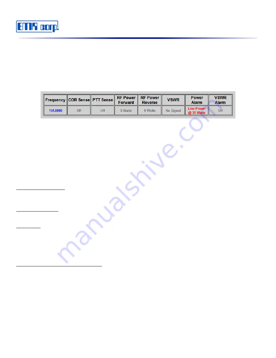
The web page should also display an alarm (see Fig. 20). 

Now clear the alarm by clicking the “Clear Alarm” submit button on the web page.

To check the Alarm  Relay operation,  connect  an  Ohm Meter   or  a  Continuity test  unit  on  pins  5 and  7 of  the  
accessory connector. Trip the alarm again by keying and unkeying the transmitter as described above. When in the 
alarm state you should read close to zero ohms or continuity. 

Now clear the alarm using the Alarm Reset located on the front panel. It will take two presses to clear the alarm.
 

Web Interface Access

The iPM-1 is entirely setup and controlled from the web. Once hooked up the network via Ethernet cable navigate to  
the   default   IP   address   to   access   the   interface.   The   default   IP   for   accessing   the   web   interface   is: 
http://192.168.3.250.

Logging In

Load the web browser & navigate to the web page by entering the IP address of the unit in the URL  to access the 
web page. The user will be prompted for a user name and a password. The User Name is always “admin” and the 
default password is “admin”.

Viewing Current Readings and Alarms

The home page (see Fig. 21) provides an almost real time display of the current readings of Forward/Reverse 
Power, VSWR and Power/VSWR Alarm status. Also, line charts of the last 24 readings are displayed for Forward/ 
Reverse Power & VSWR.

Note: Charts are static and can be reloaded by clicking the “Refresh Chart” button.

If the accessory output for Push To Talk (PTT) is connected and programmed correctly the user may click the “PTT  
Test” button to key up the transmitter for a user programmable time to test the transmitter remotely.  Also PTT Sense 
and COR (Carrier on Receive) status is viewed here.  

12

Fig. 20

Содержание iPM-1 Series

Страница 1: ...MODEL SERIES iPM 1 RF POWER MONITOR USER S MANUAL EMR CORPORATION 17431 N 25th Avenue 85027 Phoenix Arizona Tel 623 581 2875 Fax 623 582 9499 www emr com info emr com...

Страница 2: ...ming the iPM 1 2 Bench Testing 10 Web Interface Access 12 Logging In 12 Viewing Current Readings and Alarms 12 Power Sensor and Alarm Setup 13 PTT Test Setup 15 PTT Sense Setup 16 COR Sense Setup 17 I...

Страница 3: ...or a Crossover Cable 4 A standard Web Browser 5 12 to 15 Vdc power Supply Getting started Many of the iPM 1 s features are dependent upon the user s particular situation This documentation starts by...

Страница 4: ...he iPM 1 s default IP Address is set at 192 168 3 250 This will require that the computer used for access has it s IP address set to the same subnet 192 168 3 10 for example Once connected via the Cro...

Страница 5: ...ing Power VSWR Alarm COR and PTT States Also Charts of Forward Reverse Power and VSWR of the last 24 Readings with Time and Date of the Power Sensor Power Sensor Test PTT Setup This page is for enteri...

Страница 6: ...erver 1 208 200 23 20 Password q1234T Email to tech xyz com To continue with the setup process click on IP Setup Ensure that DHCP Server is disabled Now enter the IP Address Subnet Default Gateway inf...

Страница 7: ...17431 N 25th Avenue Phoenix Arizona 85023 Phone 623 581 2875 Toll Free 800 796 2875 Fax 623 582 9499 info emrcorp com www emrcorp com 5 Fig 4 Fig 5...

Страница 8: ...setup page and enter the DNS information see Fig 6 and click Submit Now enter in the Email Information see Fig 7 and click Submit Assuming that you have access to the 192 168 100 xxx LAN you may now...

Страница 9: ...ton see Fig 8 If the test was successful a message is displayed see Fig 9 If the email failed a message is also displayed see Fig 10 Enter the GMT Time and Date In the example below Fig 11 the time is...

Страница 10: ...t is assumed that this unit is to be installed to a VHF Repeater and that the installing technician has identified and pre wired the accessory cable for PTT PTT Sense COR Sense see Fig 17 and Fig 37 A...

Страница 11: ...Debounce should be enabled if you experience false readings usually not required Next we will configure the COR Sense Setup In our example the COR line will go High when a carrier is received so click...

Страница 12: ...ing are both N Since we will be sending email to just one address check the box labeled 1 in the Email Table see Fig 16 Note The Frequency text Box is used for user identification only It can also be...

Страница 13: ...ansmitter Note There is latency on the home web page Readings are delayed Next test the COR Sense by applying a high 5 Vdc to the COR Sense line The Reading should change from Off to On Now tie the PT...

Страница 14: ...up the network via Ethernet cable navigate to the default IP address to access the interface The default IP for accessing the web interface is http 192 168 3 250 Logging In Load the web browser naviga...

Страница 15: ...75 Toll Free 800 796 2875 Fax 623 582 9499 info emrcorp com www emrcorp com Power Sensor and Alarm Setup By clicking on the Power Sensor Tests PTT Link on the left frame of the web page the Power Sens...

Страница 16: ...check box is only displayed after Alarm check box Y and has been submitted Continuous Transmitter Click the Y radio button if the unit is monitoring a Continuous Transmitter This will allow an alarm o...

Страница 17: ...ith email address 1 up to email address 5 If none are checked no email notifications will be sent PTT Test Set up By clicking on the Power Sensor Tests PTT Link on the left frame of the web page the P...

Страница 18: ...ill enter the alarm mode and a Time Date stamped entry of the alarm type is entered to the Log Also when this feature is enabled check boxes are displayed in the email address that will allow report e...

Страница 19: ...radio button to disable Debounce COR Sense Setup By clicking on the Power Sensor Tests PTT Link on the left frame of the web page the Power Sensor Tests PTT page is displayed see Fig 22 COR Sense can...

Страница 20: ...ttom of the page to save any changes IP Setup By clicking on the IP Setup Link on the left frame of the web page the IP Setup page is displayed see Fig 26 The User can Enter Program the following Unit...

Страница 21: ...s achieved by the IP address If Dynamic Host Configuration Protocol DHCP is Enabled the IP address could change and make accessing the iPM 1 difficult Click the Enable radio button to enable DHCP Clic...

Страница 22: ...ings are disabled by default Static DNS Server Setup To setup Static DNS Server first disable automatic DNS Server option submit changes then insert desired Static DNS settings and submit changes agai...

Страница 23: ...Enter the email port number here Email User Name Enter the email user name for the above email server here Email Password Enter the password for the above email user name here To Email Address Enter u...

Страница 24: ...five To Email Address From the drop down box see Fig 34 select by the number which email is to be tested then click the Test Email submit button A message will be displayed below stating if the email...

Страница 25: ...d Charts are in GMT If the time is to be set manually Sync with NIST should be unchecked and Submitted This will allow both the GMT Time and Date text boxes to be edited GMT Time Enter the current GMT...

Страница 26: ...e box is left unchecked Click the Submit below the table to save any changes Installation General Connections to the transmitter receiver and DC power are grouped on a detachable accessory connector o...

Страница 27: ...talling a 2 Amp Fuse assembly is recommended on the A Lead Input and Output Requirements Most modern repeater base stations have accessory connectors to simplify installing optional equipment such as...

Страница 28: ...Detect 1 Locate the Carrier on Receive Point of the receiver this can also be PL DPL detect Audio mute etc any signal that detects that the radio is receiving a signal Carrier Detect is best since th...

Страница 29: ...17431 N 25th Avenue Phoenix Arizona 85023 Phone 623 581 2875 Toll Free 800 796 2875 Fax 623 582 9499 info emrcorp com www emrcorp com 27 Fig 37...

Страница 30: ...back to the alarm state 2 Logging onto the web page and clicking the clear Alarm Submit button in the left frame In both cases a time and date stamp of how the alarm was cleared is written to the log...

Страница 31: ...t the unit back to the factory settings the unit can be reset by the following steps 1 Remove DC Power 2 Hold down the Alarm Reset Button on the front panel 3 Apply DC Power 4 After approximately 4 se...

Страница 32: ...mrcorp com info emrcorp com Model Product Serial Sales Order Invoice __________________________________________________________ __________________________________________________________ _____________...

Отзывы: